Classification and combat properties of anti-aircraft missile systems
Anti-aircraft missile weapons are classified as surface-to-air missiles and are designed to destroy enemy air attack weapons with anti-aircraft guided missiles (SAM). It is represented by various systems.
An anti-aircraft missile system (anti-aircraft missile system) is a combination of an anti-aircraft missile system (SAM) and the means to ensure its use.
Anti-aircraft missile system - a set of functionally related combat and technical means designed to engage air targets with anti-aircraft guided missiles.
The structure of the air defense missile system includes means of detection, identification and target designation, means of flight control of missiles, one or several launchers (PU) with missiles, technical means and electrical power supplies.
The technical basis of the air defense missile system is the SAM control system. Depending on the adopted control system, there are complexes of telecontrol of missiles, homing missiles, combined control of missiles. Each air defense system has certain combat properties, features, the totality of which can serve as classification signs that allow it to be attributed to a certain type.
The combat properties of the air defense missile system include all-weather, noise immunity, mobility, versatility, reliability, the degree of automation of combat operations, etc.
All-weather - the ability of an air defense system to destroy air targets in any weather conditions. Distinguish air defense systems all-weather and non-weather. The latter ensure the destruction of targets under certain weather conditions and time of day.
Interference immunity is a property that allows an air defense system to destroy air targets in conditions of interference created by the enemy to suppress electronic (optical) means.
Mobility is a property that manifests itself in transportability and the time of transition from the traveling position to the combat position and from the combat to the traveling one. A relative indicator of mobility can be the total time required to change the starting position under given conditions. Maneuverability is part of mobility. The most mobile is considered to be a complex that has greater transportability and requires less time to maneuver. Mobile complexes can be self-propelled, towed and portable. Non-mobile air defense systems are called stationary.
Versatility is a property that characterizes technical capabilities SAM to destroy air targets in a wide range of ranges and altitudes.
Reliability is the ability to function normally under specified operating conditions.
According to the degree of automation, anti-aircraft missile systems are distinguished: automatic, semi-automatic and non-automatic. In automatic air defense systems, all operations for detecting, tracking targets and guiding missiles are performed by automatic machines without human intervention. In semi-automatic and non-automatic air defense systems, a person takes part in solving a number of tasks.
Anti-aircraft missile systems are distinguished by the number of target and missile channels. Complexes that provide simultaneous tracking and shelling of one target are called single-channel, and multiple targets are called multi-channel.
In terms of firing range, the complexes are subdivided into long-range air defense systems (DD) with a firing range of more than 100 km, medium range(SD) with a firing range of 20 to 100 km, short range(MD) with a firing range of 10 to 20 km and short-range (BD) with a firing range of up to 10 km.
The performance characteristics of the anti-aircraft missile system
The tactical and technical characteristics (TTX) determine the combat capabilities of the air defense system. These include: the purpose of the air defense missile system; range and height of destruction of air targets; the ability to destroy targets flying at different speeds; the probability of hitting air targets in the absence and presence of interference, when firing at maneuvering targets; the number of target and missile channels; anti-jamming system; working time of the air defense missile system (reaction time); the time of the transfer of the air defense system from the traveling position to the combat position and vice versa (the time of the deployment and folding of the air defense system at the starting position); movement speed; missile ammunition; power reserve; mass and dimensional characteristics, etc.
The performance characteristics are set in the tactical and technical assignment for the creation of a new sample of the air defense missile system and are specified in the process of field tests. The values of the performance characteristics are due to the design features of the elements of the air defense missile system and the principles of their operation.
The purpose of the air defense system- a generalized characteristic indicating the combat missions solved by this type of air defense system.
Range of defeat(shooting) - the range at which targets are hit with a probability not lower than the specified one. Distinguish between minimum and maximum ranges.
Height of defeat(shooting) - the height at which targets are hit with a probability not lower than the specified one. Distinguish between minimum and maximum heights.
The ability to destroy targets flying at different speeds is a characteristic indicating the maximum permissible value of the flight speeds of targets that are destroyed in a given range of ranges and altitudes. The magnitude of the target's flight speed determines the values of the necessary rocket overloads, dynamic guidance errors and the probability of hitting the target with one missile. At high target speeds, the necessary missile overloads, dynamic guidance errors increase, and the likelihood of destruction decreases. As a result, the values of the maximum range and target destruction altitude decrease.
Target hitting probability- a numerical value characterizing the possibility of hitting a target under given firing conditions. Expressed as a number between 0 and 1.
The target can be hit when firing one or more missiles, therefore, the corresponding probability of hitting P is considered. ; and P NS .
Target channel- a set of elements of the air defense system, providing simultaneous tracking and shelling of one target. Distinguish between single-channel and multi-channel air defense systems for the purpose. The N-channel target complex allows you to simultaneously fire at N targets. The target channel includes a sighting device and a device for determining the coordinates of the target.
Rocket channel- a set of elements of the air defense missile system, which simultaneously provides preparation for the start, start and guidance of one missile defense system at the target. The missile channel includes: a launcher (launcher), a device for preparing for the launch and launch of missile defense systems, a sighting device and a device for determining the coordinates of a missile, elements of a device for forming and transmitting missile control commands. An integral part of the missile channel is a missile defense system. SAMs in service are single and multi-channel. Single-channel are performed portable complexes... They allow only one missile to be aimed at the target at a time. Multi-channel missile systems provide simultaneous firing of one or more targets with several missiles. Such air defense systems have great opportunities for consistent firing at targets. To obtain a given value of the probability of destroying a target, the air defense system has 2-3 missile channels per target channel.
As an indicator of interference immunity, the following are used: the interference immunity coefficient, the permissible interference power density at the far (near) border of the affected zone in the area of the jammer, at which timely detection (opening) and destruction (destruction) of the target is ensured, the range of the open zone, the range from which the target is detected (revealed) against the background of interference when the producer sets up interference.
SAM working hours(reaction time) - the time interval between the moment an air target is detected by the air defense system and the launch of the first missile. It is determined by the time it takes to find and lock the target and to prepare the initial data for shooting. The working time of the air defense system depends on the design features and characteristics of the air defense system from the level of training of the combat crew. For modern air defense systems, its value ranges from units to tens of seconds.
The time of transfer of the air defense system from the traveling position to the combat position- the time from the moment the command is given to transfer the complex to a combat position until the complex is ready to open fire. For MANPADS, this time is minimal and amounts to a few seconds. The time to transfer the air defense system to the firing position is determined by the initial state of its elements, the transfer mode and the type of power source.
Time of transfer of the air defense system from combat position in the field- the time from the moment the command was given to transfer the air defense system to the stowed position until the end of the construction of the elements of the air defense missile system in the marching column.
Combat kit(bk) - the number of missiles installed on one air defense system.
Power reserve- the maximum distance that an air defense vehicle vehicle can travel, having consumed a full refueling of fuel.
Mass characteristics- limiting mass characteristics of elements (cabins) of air defense missile systems and missiles.
Dimensional characteristics- the limiting external outlines of the elements (cabins) of the air defense missile system and the air defense missile system, determined by the maximum width, length and height.
SAM defeat zone
The affected area of the complex is the area of space within which the defeat of an air target by an anti-aircraft guided missile is ensured under the design conditions of firing with a given probability. Taking into account the effectiveness of firing, it determines the reach of the complex in terms of height, range and heading parameter.
Estimated shooting conditions- conditions under which the angles of closing the position of the air defense missile system are equal to zero, the characteristics and parameters of the target's movement (its effective reflecting surface, speed, etc.) do not go beyond the specified limits, atmospheric conditions do not interfere with the observation of the target.
Realizable affected area- a part of the affected area, in which the destruction of a target of a certain type is ensured in specific conditions of firing with a given probability.
Shelling area- the space around the air defense system, in which the missile is guided to the target.
Rice. 1. The affected area of the air defense missile system: vertical (a) and horizontal (b) section
The affected area is depicted in a parametric coordinate system and is characterized by the position of the far, near, upper and lower boundaries. Its main characteristics are: horizontal (oblique) range to far and near boundaries d d (D d) and d (D), minimum and maximum heights H mn and H max, limiting course angle q max and maximum elevation angle s max. The horizontal range to the far border of the affected area and the limiting heading angle determine the limiting parameter of the affected area P, i.e., the maximum target parameter, at which its defeat is ensured with a probability not lower than the specified one. For multichannel target air defense systems, the characteristic value is also the parameter of the affected area Pstro, up to which the number of firing at the target is not less than with a zero parameter of its movement. A typical section of the affected area with the vertical bisector and horizontal planes is shown in the figure.
The position of the boundaries of the affected area is determined by a large number of factors related to the technical characteristics of individual elements of the air defense system and the control loop as a whole, the conditions of firing, the characteristics and parameters of the movement of the air target. The position of the far border of the affected area determines the required range of the SNR.
The position of the realizable far and lower boundaries of the affected area of the air defense missile system may also depend on the terrain.
SAM launch zone
In order for the missile to meet with the target in the affected area, the missile must be launched in advance, taking into account the flight time of the missile and the target to the meeting point.
The missile launch zone is an area of space, when a target is located in which, at the time of launching missiles, they meet in the affected area of the air defense missile system. To determine the boundaries of the launch zone, it is necessary to set aside from each point of the affected zone to the side opposite to the target's course, a segment equal to the product of the target's velocity V ii for the flight time of the rocket to a given point. In the figure, the most characteristic points of the launch zone are respectively designated by the letters a ", 6" in "d" e ".

Rice. 2. ZRK launch zone (vertical section)
When tracking a target with a SNR, the current coordinates of the rendezvous point, as a rule, are calculated automatically and displayed on the indicator screens. The missile is launched when the meeting point is within the boundaries of the affected area.
Guaranteed launch area- the area of space, when a target is found in which at the time of launching a missile, it is ensured that it meets with a target in the affected area, regardless of the type of anti-missile maneuver of the target.
Composition and characteristics of elements of anti-aircraft missile systems
In accordance with the tasks to be solved, the functionally necessary elements of the air defense missile system are: means of detection, identification of aircraft and target designation; SAM flight controls; launchers and launchers; anti-aircraft guided missiles.
To combat low-flying targets, portable anti-aircraft missile systems (MANPADS) can be used.
When used as part of air defense missile systems (Patriot, S-300) multifunctional radars, they act as means of detection, identification, tracking devices for aircraft and missiles aimed at them, control command transmission devices, as well as target illumination stations to ensure the operation of on-board radio direction finders.
Detection tools
In anti-aircraft missile systems, radar stations, optical and passive direction finders can be used as aircraft detection means.
Optical detection equipment (OSS). Depending on the location of the source of radiation of radiant energy, optical detection means are subdivided into passive and semi-active. In passive OCAs, as a rule, radiant energy is used due to heating of the aircraft skin and operating engines, or light energy The sun reflected from the aircraft. An optical quantum generator (laser) is located in the semi-active CCOs at the ground control station, the energy of which is used to probe space.
Passive CCA is a television-optical sighting device, which includes a transmitting television camera (PTK), a synchronizer, communication channels, and a video control device (VCU).
The TV-optical sighting device converts the flow of light (radiant) energy coming from the aircraft into electrical signals, which are transmitted through the cable communication line and are used in the VKU to reproduce the transmitted image of the aircraft, which is in the field of view of the PTC lens.
In the transmitting television tube, the optical image is converted into an electrical one, while a potential relief appears on the photomosaic (target) of the tube, which reflects the distribution of the brightness of all points of the aircraft in electrical form.
The potential relief is read by the electron beam of the transmitting tube, which, under the action of the field of the deflecting coils, moves synchronously with the electron beam of the VCU. On the load resistance of the transmitting tube, the video signal of the image arises, which is amplified by the pre-amplifier and is fed to the VCU via the communication channel. After amplification in the amplifier, the video signal is fed to the control electrode of the receiving tube (kinescope).
Synchronization of the motion of the PTC and VCU electron beams is carried out by line and frame scan pulses, which are not mixed with the image signal, but are transmitted via a separate channel.
The operator observes on the screen of the picture tube the images of the aircraft in the field of view of the sighting lens, as well as the sighting marks corresponding to the position of the optical axis of the TOV in azimuth (b) and elevation (e), as a result of which the azimuth and elevation of the aircraft can be determined.
Semi-active CCA (laser sighting devices) are almost completely analogous to radar ones in their structure, principles of construction and performed functions. They allow you to determine the angular coordinates, range and speed of the target.
A laser transmitter is used as a signal source, which is triggered by a synchronizer pulse. The laser light signal is emitted into space, reflected from the aircraft and received by the telescope.
 Radar detection equipment
A narrow-band filter, standing in the path of the reflected pulse, reduces the effect of extraneous light sources on the operation of the sight. Light pulses reflected from the aircraft fall on a photosensitive receiver, converted into video frequency signals and used in units for measuring angular coordinates and range, as well as for displaying an indicator on the screen.
In the unit for measuring angular coordinates, signals are generated to control the drives of the optical system, which provide both an overview of the space and automatic tracking of the aircraft in angular coordinates (continuous alignment of the axis of the optical system with the direction to the aircraft).
Aircraft identification means
The means of identification make it possible to determine the nationality of the detected aircraft and classify it as "friend or foe". They can be combined and stand-alone. In co-located devices, request and response signals are emitted and received by radar devices.


"Top-M1" detection radar antenna Optical detection equipment

Radar-optical detection equipment
A receiver of interrogation signals is installed on "own" aircraft, which receives coded interrogation signals sent by the detection (identification) radar. The receiver decodes the interrogation signal and, when this signal corresponds to the set code, sends it to the response signal transmitter installed on board "its" aircraft. The transmitter generates a coded signal and sends it in the direction of the radar, where it is received, decoded and, after conversion, is output to the indicator in the form of a conventional mark, which is displayed next to the mark from “its” aircraft. The enemy aircraft does not respond to the radar request signal.
Target designation means
Target designation means are intended for receiving, processing and analyzing information about the air situation and determining the sequence of firing at detected targets, as well as transmitting data about them to other combat assets.
Information about detected and identified aircraft, as a rule, comes from the radar. Depending on the type of target designation terminal device, the analysis of information about the aircraft is carried out automatically (when using a computer) or manually (by an operator when using screens of cathode ray tubes). The results of the decision of the computer (calculating device) can be displayed on special consoles, indicators or in the form of signals for the operator to make a decision on their further use, or transmitted to other combat assets of the air defense missile system automatically.
If the screen is used as terminal devices, then the marks from the detected aircraft are displayed with light signs.
Target designation data (decisions on target firing) can be transmitted both via cable lines and radio communication lines.
Target designation and detection means can serve as one or several units of air defense missile systems.
SAM flight controls
When an aircraft is detected and identified, the analysis of the air situation, as well as the order of firing at targets, is carried out by the operator. At the same time, devices for measuring range, angular coordinates, speed, forming control commands and transmitting commands (command radio control line), an autopilot and a rocket steering tract are involved in the operation of the flight control devices of the missile defense system.
The range measuring device is designed to measure the slant range to aircraft and missiles. Determination of the range is based on the straightness of propagation of electromagnetic waves and the constancy of their speed. The range can be measured by location and optical means. For this, the signal travel time from the radiation source to the aircraft and back is used. Time can be measured by the delay of the pulse reflected from the aircraft, the amount of change in the frequency of the transmitter, the amount of change in the phase of the radar signal. Information about the range to the target is used to determine the moment of launching the missile defense system, as well as to generate control commands (for systems with telecontrol).
The angular coordinate measuring device is designed to measure the elevation (e) and azimuth (b) of aircraft and missiles. The measurement is based on the property of rectilinear propagation of electromagnetic waves.
The speed measuring device is designed to measure the radial speed of the aircraft. The measurement is based on the Doppler effect, which consists in changing the frequency of the reflected signal from moving objects.
The control command generation device (UFK) is designed to generate electrical signals, the magnitude and sign of which correspond to the magnitude and sign of the missile's deviation from the kinematic trajectory. The magnitude and direction of the deflection of the missile defense system from the kinematic trajectory are manifested in the violation of the connections caused by the nature of the target's movement and the method of aiming the missile defense system on it. The measure of violation of this connection is called the mismatch parameter A (t).
The value of the mismatch parameter is measured by means of tracking the SAM, which, based on A (t), generate a corresponding electrical signal in the form of voltage or current, called the mismatch signal. The error signal is the main component in the formation of the control command. To improve the accuracy of guiding the missile to the target, some correction signals are introduced into the control team. In telecontrol systems, when implementing the three-point method, in order to reduce the time of launching a rocket to the meeting point with a target, as well as to reduce errors in guiding the rocket to a target, a damping signal and a signal to compensate for dynamic errors caused by the movement of the target, the mass (weight) of the rocket can be included in the control command ...
Control command transmission device (command radio control lines). In telecontrol systems, the transmission of control commands from the guidance point to the on-board missile defense device is carried out by means of equipment that forms a command radio control line. This line provides the transmission of missile flight control commands, one-time commands that change the operating mode of the onboard equipment. The command radio link is a multichannel communication line, the number of channels of which corresponds to the number of commands transmitted while simultaneously controlling several missiles.
The autopilot is designed to stabilize the angular movements of the rocket relative to the center of mass. In addition, the autopilot is an integral part of the missile flight control system and controls the position of the center of mass itself in space in accordance with control commands.
Launchers, launchers
Launchers (PU) and launchers are special devices designed for placement, aiming, prelaunch preparation and missile launch. PU consists of a launch pad or guides, guidance mechanisms, leveling means, testing and starting equipment, power supplies.
Launchers are distinguished by the type of missile launch - with a vertical and oblique launch, by mobility - stationary, semi-stationary (collapsible), mobile.

Stationary launcher C-25 with vertical launch

Igla portable anti-aircraft missile system

Launcher of a portable anti-aircraft missile system "Bloupipe" with three guides
Stationary launchers in the form of launchers are mounted on special concreted areas and cannot be moved.
Semi-stationary launchers, if necessary, can be disassembled and, after transportation, installed in another position.
Mobile launchers are placed on special vehicles. They are used in mobile air defense systems and are carried out in self-propelled, towed, portable (portable) versions. Self-propelled launchers are placed on tracked or wheeled chassis, providing a quick transition from the traveling position to the combat position and vice versa. Towed launchers are installed on tracked or wheeled non-self-propelled chassis, transported by tractors.
Portable launchers are made in the form of launch tubes, into which the rocket is installed before launch. The launch tube can have an aiming device for pre-aiming and a trigger.
By the number of missiles on the launcher, single launchers are distinguished, paired, etc.
Anti-aircraft guided missiles
Anti-aircraft guided missiles are classified according to the number of stages, aerodynamic configuration, guidance method, and type of warhead.
Most missiles can be one- and two-stage.
According to the aerodynamic scheme, missiles are distinguished, made according to the normal scheme, according to the "rotary wing" scheme, and also according to the "duck" scheme.
By the method of guidance, a distinction is made between homing and remote-controlled missiles. A self-guided missile is a missile with flight control equipment installed on board. Telecontrolled missiles are called missiles, guided (guided) by ground control (guidance).
By the type of warhead, SAMs with conventional and nuclear warheads are distinguished.

Self-propelled PU SAM "Buk" with an inclined start

Semi-stationary launcher S-75 air defense missile system with inclined launch

Self-propelled PU SAM S-300PMU with vertical launch
Portable anti-aircraft missile systems
MANPADS are designed to combat low-flying targets. The basis for the construction of MANPADS can be a passive homing system ("Stinger", "Strela-2, 3", "Igla"), a radio command system ("Blupipe"), a laser guidance system (RBS-70).
MANPADS with a passive homing system include a launcher (launch container), a launcher, identification equipment, and an anti-aircraft guided missile.
The launcher is a sealed fiberglass tube in which the missile defense system is stored. The pipe is sealed. Outside the tube are sights for preparing a missile launch and a launcher.
The launching mechanism ("Stinger") includes an electric battery for powering the equipment of both the mechanism itself and the homing head (before launching the rocket), a refrigerant cylinder for cooling the receiver of thermal radiation of the seeker during preparation of the rocket for launch, a switching device that provides the necessary sequence passing of commands and signals, indicator device.
The identification equipment includes an identification antenna and an electronic unit, which includes a transceiver device, logic circuits, a computing device, and a power supply.
The rocket (FIM-92A) is single-stage, solid-propellant. The seeker can operate in the infrared and ultraviolet ranges, the radiation receiver is cooled. The alignment of the axis of the optical system of the seeker with the direction to the target during its tracking is carried out using a gyroscopic drive.
A rocket is launched from a container using a launch booster. The cruise engine is turned on when the rocket has moved away to a distance at which it is excluded that the anti-aircraft gunner is hit by the jet of the operating engine.
The radio command MANPADS includes a transport and launch container, a guidance unit with identification equipment and an anti-aircraft guided missile. The connection of the container with the missile and the guidance unit located in it is carried out in the process of preparing the MANPADS for combat use.
There are two antennas on the container: one - command transmission devices, the other - identification equipment. Inside the container is the rocket itself.
Aiming unit includes a monocular optical sight, ensuring the capture and tracking of the target, an IR device for measuring the deviation of the missile from the line of sight of the target, a device for generating and transmitting guidance commands, a program device for preparing and executing a launch, an interrogator of the “friend or foe” identification equipment. There is a controller on the body of the unit, which is used when aiming a missile at a target.
After launching the missile defense system, the operator accompanies it in the radiation of the tail IR tracer using an optical sight. The launch of the missile to the line of sight is carried out manually or automatically.
In automatic mode, the deviation of the missile from the line of sight, measured by the IR device, is converted into guidance commands transmitted to the missile system. The IR device is turned off after 1-2 seconds of flight, after which the rocket is guided to the meeting point manually, provided that the operator achieves the alignment of the target and rocket images in the sight of the sight by changing the position of the control switch. Control commands are transmitted on board the missile defense system, ensuring its flight along the required trajectory.
In the complexes that provide guidance to the missile along a laser beam (RBS-70), laser receivers are placed in the tail compartment of the missile to guide the missile at the target, which generate signals that control the missile's flight. The guidance unit includes an optical sight, a device for forming a laser beam with a focusing variable depending on the distance from the missile defense system.
Anti-aircraft missile control systems Telecontrol systems
Telecontrol systems are those in which the movement of the rocket is determined by a ground guidance point, which continuously monitors the parameters of the trajectory of the target and the rocket. Depending on the location of the formation of commands (signals) to control the rudders of the rocket, these systems are divided into beam guidance systems and command telecontrol systems.
In beam guidance systems, the direction of the rocket is set using directional radiation of electromagnetic waves (radio waves, laser radiation, etc.). The beam is modulated in such a way that when the missile deviates from a given direction, its onboard devices automatically detect the mismatch signals and generate the appropriate missile control commands.
An example of the use of such a control system with teleorientation of a missile in a laser beam (after it has been launched into this beam) is the ADATS multipurpose missile system, developed by the Swiss company Oerlikon together with the American Martin Marietta. It is believed that this method of control, in comparison with the command telecontrol system of the first type, provides a higher accuracy of guiding the missile to the target at long ranges.
In command telecontrol systems, missile flight control commands are generated at the guidance point and transmitted to the missile board via a communication line (telecontrol line). Depending on the method of measuring the coordinates of the target and determining its position relative to the missile, the command telecontrol systems are divided into telecontrol systems of the first type and telecontrol systems of the second type. In systems of the first type, the current coordinates of the target are measured directly by the ground guidance point, and in systems of the second type - by the onboard missile coordinator with their subsequent transfer to the guidance point. The development of missile control commands both in the first and in the second case is carried out by a ground guidance point.

Rice. 3. Command telecontrol system
Determination of the current coordinates of the target and missile (for example, range, azimuth and elevation) is carried out by the tracking radar. In some complexes, this task is solved by two radars, one of which accompanies the target (radar 7 sighting the target), and the other - the missile (radar 2 sighting the missile).
Target sighting is based on the use of the principle of active radar with a passive response, i.e., on obtaining information about the current coordinates of the target from radio signals reflected from it. Target tracking can be automatic (AC), manual (PC) or mixed. Most often, target scopes have devices that provide various types of target tracking. Automatic tracking is carried out without the participation of the operator, manual and mixed - with the participation of the operator.
To sight missiles in such systems, as a rule, radar lines with an active response are used. A transceiver is installed on board the rocket, which emits response pulses to the request pulses sent by the guidance point. This method of sighting the missile ensures its stable automatic tracking, including when firing at significant ranges.
The measured values of the coordinates of the target and the rocket are fed to the command generation device (CGD), which can be performed on the basis of a digital computer or in the form of an analog calculating device. Formation of teams is carried out in accordance with the selected guidance method and the adopted mismatch parameter. The control commands generated for each guidance plane are encrypted and sent to the missile board by the command radio transmitter (RPK). These commands are received by the onboard receiver, amplified, deciphered and, through the autopilot, in the form of certain signals that determine the magnitude and sign of rudder deflection, are issued to the rocket rudders. As a result of turning the rudders and the appearance of angles of attack and slip, lateral aerodynamic forces arise, which change the direction of the rocket's flight.
The missile control process is carried out continuously until it meets the target.
After the launch of the missile to the target area, as a rule, with the help of a proximity fuse, the task of choosing the moment of detonation of the warhead of an anti-aircraft guided missile is solved.
The command telecontrol system of the first type does not require an increase in the composition and mass of onboard equipment, it has greater flexibility in the number and geometry of possible missile trajectories. The main disadvantage of the system is the dependence of the linear error of guiding the missile at the target on the firing range. If, for example, the value of the angular guidance error is assumed to be constant and equal to 1/1000 of the range, then the missile miss at firing ranges of 20 and 100 km, respectively, will be 20 and 100 m. the launch mass of the rocket. Therefore, the telecontrol system of the first type is used to defeat the targets of missiles at short and medium ranges.
In the first type of telecontrol system, the target and missile tracking channels and the radio control line are exposed to interference. Foreign experts associate the solution to the problem of increasing the noise immunity of this system with the use, including in a complex manner, of target and missile sighting channels (radar, infrared, visual, etc.) different in frequency range and operating principles, as well as radar stations with a phased antenna array ( PAR).

Rice. 4. Command telecontrol system of the second type
The coordinator (radio direction finder) of the target is installed on board the missile. It monitors the target and determines its current coordinates in a moving coordinate system associated with the missile. The coordinates of the target are transmitted via the communication channel to the guidance point. Therefore, the on-board radio direction finder generally includes an antenna for receiving target signals (7), a receiver (2), a device for determining the coordinates of a target (3), an encoder (4), a transmitter of signals (5) containing information about the coordinates of a target, and a transmitting antenna ( 6).
The coordinates of the target are taken by the ground guidance point and fed to the control command generation device. The current coordinates of the anti-aircraft guided missile are also received from the missile escort station (radio viewer) to the UVK. The command generating device determines the mismatch parameter and generates control commands, which, after appropriate transformations by the command transmission station, are issued to the missile board. To receive these commands, transform them and test them by the rocket, the same equipment is installed on board as in the first type of telecontrol systems (7 - command receiver, 8 - autopilot). The advantages of the second type of telecontrol system are the independence of the missile guidance accuracy from the firing range, an increase in the resolution as the missile approaches the target and the possibility of targeting the required number of missiles.
The disadvantages of the system include an increase in the cost of an anti-aircraft guided missile and the impossibility of manual target tracking modes.
In terms of its structural diagram and characteristics, the telecontrol system of the second type is close to homing systems.
Homing systems
Homing is the automatic guidance of a missile to a target, based on the use of energy going from the target to the missile.
The missile homing head autonomously tracks the target, determines the mismatch parameter and generates missile control commands.
According to the type of energy that the target emits or reflects, homing systems are divided into radar and optical (infrared or thermal, light, laser, etc.).
Depending on the location of the primary source of energy, homing systems can be passive, active and semi-active.
With passive homing, the energy emitted or reflected by the target is created by the sources of the target itself or by the target's natural irradiator (Sun, Moon). Consequently, information about the coordinates and parameters of the target's movement can be obtained without special irradiation of the target with energy of any kind.
An active homing system is characterized by the fact that the energy source that irradiates the target is installed on the rocket and the energy of this source reflected from the target is used for homing the missile defense system.
In semi-active homing, the target is irradiated by a primary energy source located outside the target and the missile (Hawk air defense missile system).
Radar homing systems have become widespread in air defense systems due to their practical independence of action from meteorological conditions and the possibility of guiding a missile to a target of any type and at various ranges. They can be used on all or only on the final section of the trajectory of an anti-aircraft guided missile, i.e., in combination with other control systems (telecontrol system, programmed control).
In radar systems, the use of passive homing is very limited. This method is possible only in special cases, for example, when a missile defense system is homing at an aircraft that has a continuously operating jamming radio transmitter on board. Therefore, in radar homing systems, special irradiation ("highlighting") of the target is used. When the missile is homing along the entire segment of its flight path to the target, as a rule, in terms of energy and cost ratios, semi-active homing systems are used. The primary source of energy (target illumination radar) is usually located at the guidance point. Combined systems use both semi-active and active homing systems. The limitation on the range of the active homing system occurs due to the maximum power that can be obtained on the rocket, taking into account the possible dimensions and weight of the onboard equipment, including the homing head antenna.
If homing does not start from the moment the rocket starts, then with an increase in the firing range of the rocket, the energy advantages of active homing in comparison with semi-active homing increase.
To calculate the misalignment parameter and generate control commands, the tracking systems of the seeker must continuously track the target. In this case, the formation of a control command is possible with target tracking only in angular coordinates. However, such tracking does not provide target selection in terms of range and speed, as well as protection of the seeker receiver from side information and interference.
Equal signal methods of direction finding are used for automatic tracking of the target in angular coordinates. The angle of arrival of the wave reflected from the target is determined by comparing the signals received from two or more mismatched radiation patterns. The comparison can be carried out simultaneously or sequentially.
The most widespread are direction finders with an instantaneous equal-signal direction, in which a sum-difference method is used to determine the angle of deflection of a target. The emergence of such direction finding devices is primarily due to the need to improve the accuracy of automatic target tracking systems in the direction. Such direction finders are theoretically insensitive to amplitude fluctuations of the signal reflected from the target.
In direction finders with an equal-signal direction, created by periodically changing the antenna pattern, and, in particular, with a scanning beam, a random change in the amplitudes of the signal reflected from the target is perceived as a random change in the angular position of the target.
The principle of target selection in terms of range and speed depends on the nature of the radiation, which can be pulsed or continuous.
With pulsed radiation, target selection is carried out, as a rule, in terms of range using strobe pulses that open the seeker's receiver at the time of arrival of signals from the target.

Rice. 5. Radar semi-active homing system
With continuous radiation, it is relatively easy to select a target by speed. The Doppler effect is used to track the target in speed. The magnitude of the Doppler frequency shift of the signal reflected from the target is proportional with active homing to the relative speed of the missile's approach to the target, and with semi-active homing, the radial component of the target's velocity relative to the ground-based irradiation radar and the relative speed of the missile's approach to the target. To isolate the Doppler shift in semi-active homing on a missile after target acquisition, it is necessary to compare the signals received by the irradiation radar and the homing head. The tuned filters of the seeker receiver pass into the angle change channel only those signals that are reflected from a target moving at a certain speed relative to the missile.
With regard to the Hawk-type anti-aircraft missile system, it includes a target irradiation (illumination) radar, a semi-active homing head, an anti-aircraft guided missile, etc.
The task of the target irradiation (illumination) radar is to continuously irradiate the target with electromagnetic energy. The radar uses directional radiation of electromagnetic energy, which requires continuous tracking of the target in angular coordinates. For other tasks, target tracking in range and speed is also provided. Thus, the ground part of the semi-active homing system is a radar station with continuous automatic target tracking.
The semi-active seeker is mounted on the rocket and includes a coordinator and a calculator. It provides capture and tracking of the target in angular coordinates, range or speed (or in all four coordinates), determination of the mismatch parameter and generation of control commands.
An autopilot is installed on board the anti-aircraft guided missile, which solves the same tasks as in the command telecontrol systems.
An anti-aircraft missile system using a homing system or a combined control system also includes equipment and apparatus that provide preparation and launch of missiles, guidance of the radiation radar to a target, etc.
Infrared (thermal) homing systems for anti-aircraft missiles use a wavelength range of typically 1 to 5 microns. In this range, the maximum heat radiation of most air targets is located. The ability to use passive homing is the main advantage of infrared systems. The system is made simpler, and its operation is hidden from the enemy. It is more difficult for an air adversary to detect such a system before launching a missile defense system, and after launching a missile, create active interference with it. The receiver of the infrared system can be structurally made much simpler than the receiver of the radar seeker.
The disadvantage of the system is the dependence of the range on meteorological conditions. Heat rays are strongly attenuated in rain, fog, and clouds. The range of such a system also depends on the orientation of the target relative to the energy receiver (on the direction of reception). The radiant flux from the jet engine nozzle of the aircraft significantly exceeds the radiant flux of its fuselage.
Thermal homing heads are widely used in close-range and short-range anti-aircraft missiles.
Light homing systems are based on the fact that most aerial targets reflect sunlight or moonlight significantly more than the surrounding background. This allows you to highlight the target against a given background and aim an anti-aircraft missile at it with the help of the seeker, which receives a signal in the visible part of the electromagnetic wave spectrum.
The advantages of this system are determined by the possibility of using a passive homing method. Its significant drawback is the strong dependence of the range of action on meteorological conditions. Under good meteorological conditions, light homing is also impossible in directions where the light of the Sun and the Moon falls into the field of view of the goniometer of the system.
Combined control
Combined control means a combination different systems control when aiming a missile at a target. In anti-aircraft missile systems, it is used when firing at long ranges to obtain the required accuracy of guiding the missile to the target with permissible mass values of the missile defense system. The following sequential combinations of control systems are possible: telecontrol of the first type and homing, telecontrol of the first and second types, autonomous system and homing.
The use of combined control necessitates the solution of such problems as the conjugation of trajectories during the transition from one control method to another, ensuring the capture of the target by the missile homing head in flight, the use of the same on-board equipment devices at different stages of control, etc.
At the time of the transition to homing (telecontrol of the second type), the target should be within the radiation pattern of the receiving antenna of the seeker, the width of which usually does not exceed 5-10 °. In addition, guidance of tracking systems should be carried out: the GOS by range, by speed, or by range and speed, if target selection by these coordinates is provided to increase the resolution and noise immunity of the control system.
Guidance of the seeker at the target can be carried out in the following ways: by commands transmitted to the missile board from the guidance point; the inclusion of an autonomous automatic search for a target seeker by angular coordinates, range and frequency; a combination of preliminary command guidance of the seeker at the target with the subsequent search for the target.
Each of the first two methods has its own advantages and significant disadvantages. The task of ensuring reliable guidance of the seeker at the target during the missile's flight to the target is quite complex and may require the use of a third method. Preliminary guidance of the seeker allows you to narrow the target search range.
With a combination of telecontrol systems of the first and second types, after the onboard radio direction finder begins to operate, information can be received simultaneously from two sources: a target tracking station and a missile and an onboard radio direction finder, into the command generating device of the ground guidance point. Based on the comparison of the generated commands according to the data of each source, it is possible to solve the problem of conjugating the trajectories, as well as to increase the accuracy of the missile guidance to the target (to reduce the random components of errors by selecting a source, weighing the variances of the generated commands). This method of combining control systems is called binary control.
Combined control is used in cases where the required characteristics of the air defense system cannot be achieved using only one control system.
Autonomous control systems
Autonomous control systems are those in which flight control signals are generated on board the rocket in accordance with a pre-set program (before launch). During the flight of the rocket, the autonomous control system does not receive any information from the target and the control point. In a number of cases, such a system is used in the initial segment of the rocket's flight path to bring it into a given region of space.
Elements of missile control systems
A guided missile is an unmanned aircraft with a jet engine designed to destroy air targets. All onboard devices are located on the rocket glider.
A glider is a supporting structure of a rocket, which consists of a body, fixed and movable aerodynamic surfaces. The airframe body is usually cylindrical in shape with a conical (spherical, ogival) head.
The aerodynamic surfaces of the airframe are used to create lift and control forces. These include fenders, stabilizers (fixed surfaces), rudders. By mutual disposition rudders and fixed aerodynamic surfaces distinguish between the following aerodynamic missile schemes: normal, "tailless", "duck", "rotary wing".

Rice. b. Layout diagram of a hypothetical guided missile:
1 - rocket body; 2 - proximity fuse; 3 - rudders; 4 - warhead; 5 - tanks for fuel components; b - autopilot; 7 - control equipment; 8 - wings; 9 - sources of onboard power supply; 10 - main stage rocket engine; 11 - launch stage rocket engine; 12 - stabilizers.

Rice. 7. Aerodynamic schemes of guided missiles:
1 - normal; 2 - "tailless"; 3 - "duck"; 4 - "rotary wing".
Guided missile engines are divided into two groups: rocket and air-jet.
A rocket engine is one that uses fuel entirely on board the rocket. It does not require the intake of oxygen from the environment for its operation. According to the type of fuel, rocket engines are divided into solid propellant rocket engines (solid propellant rocket engines) and liquid propellant rocket engines (LRE). As fuel in solid propellants, rocket powder and mixed solid propellants are used, which are poured and pressed directly into the combustion chamber of the engine.
Air-jet engines (VRM) are engines in which oxygen taken from the ambient air serves as an oxidant. As a result, only fuel is contained on board the rocket, which makes it possible to increase the fuel supply. The disadvantage of the WFD is the impossibility of their operation in the rarefied layers of the atmosphere. They can be used on aircraft at flight altitudes up to 35-40 km.
Autopilot (AP) is designed to stabilize the angular movements of the rocket relative to the center of mass. In addition, the AP is an integral part of the missile flight control system and controls the position of the center of mass itself in space in accordance with control commands. In the first case, the autopilot plays the role of a missile stabilization system, in the second - the role of an element of the control system.
To stabilize the rocket in the longitudinal, azimuthal planes and when moving relative to the longitudinal axis of the rocket (along the roll), three independent stabilization channels are used: pitch, heading and roll.
Onboard missile flight control equipment is an integral part of the control system. Its structure is determined by the adopted control system implemented in the anti-aircraft and aircraft missile control complex.
In command telecontrol systems on board the rocket, devices are installed that make up the receiving path of the command radio control line (KRU). They include an antenna and a receiver for radio signals of control commands, a command selector, a demodulator.
Combat equipment of anti-aircraft and aircraft missiles - a combination of a warhead and a fuse.
The warhead has a warhead, a detonator and a body. According to the principle of operation, warheads can be fragmentation and high-explosive fragmentation. Some types of missiles can also be equipped with nuclear warheads (for example, in the Nike-Hercules air defense system).
The striking elements of the warhead are both fragments and ready-made elements placed on the surface of the hull. Blasting (crushing) explosives (TNT, mixtures of TNT with RDX, etc.) are used as warheads.
Rocket fuses can be non-contact and contact. Proximity fuses, depending on the location of the energy source used to trigger the fuse, are divided into active, semi-active and passive. In addition, proximity fuses are subdivided into electrostatic, optical, acoustic, radio fuses. In foreign missile models, radio and optical fuses are more often used. V individual cases both optical and radio fuses operate simultaneously, which increases the reliability of detonating the warhead in conditions of electronic suppression.
The operation of a radio fuse is based on the principles of radar. Therefore, such a fuse is a miniature radar that generates a detonation signal at a certain position of the target in the fuse antenna beam.
By design and principles of operation, radio fuses can be pulsed, Doppler and frequency.

Rice. 8. Block diagram of a pulsed radio fuse
In a pulsed fuse, the transmitter generates high-frequency pulses of short duration, emitted by the antenna in the direction of the target. The antenna beam is coordinated in space with the area of dispersion of the warhead fragments. When the target is in the beam, the reflected signals are received by the antenna, pass through the receiving device and enter the coincidence cascade, where a strobe pulse is fed. If they match, a signal is issued to detonate the warhead detonator. The duration of the strobe pulses determines the range of possible ranges for the fuse operation.
Doppler fuses are more likely to operate in continuous mode. The signals reflected from the target and received by the antenna are fed to the mixer, where the Doppler frequency is allocated.
At a given speed, the Doppler frequency signals pass through a filter and are fed to an amplifier. At a certain amplitude of current fluctuations of this frequency, a detonation signal is issued.
Contact fuses can be electric or shock fuses. They are used in short-range missiles with high firing accuracy, which ensures the detonation of the warhead in the event of a direct missile hit.
To increase the likelihood of hitting the target by fragments of the warhead, measures are taken to coordinate the areas of detonation of the fuse and the dispersion of the fragments. With good agreement, the area of the scattering of fragments, as a rule, coincides in space with the area of finding the target.
"Ministry of Defense of Russia"
Air defense troops appeared during the First World War. On December 26, 1915, the first four separate four-gun light batteries for firing at air targets were formed and sent to the Western Front. In accordance with the order of the Minister of Defense of the Russian Federation of February 9, 2007, this memorable date began to be celebrated in Russia as the Day military air defense.
Organizationally, these formations are part of the formations, formations and units of the Ground Forces, the Airborne Forces, the Coastal Forces of the Navy (Navy) and perform tasks in the unified air defense system of the country. They are equipped with anti-aircraft missile, anti-aircraft artillery, anti-aircraft gun-missile systems (systems) of various ranges and missile guidance methods, as well as portable weapons. Depending on the range of destruction of air targets, they are subdivided into short-range complexes - up to 10 km, short-range - up to 30 km, medium - up to 100 km, and long-range - more than 100 km.
At the final collegium of the RF Ministry of Defense held on December 22, the Commander-in-Chief of the Ground Forces, Oleg Salyukov, said that the Russian military air defense is capable of repelling any air attack weapons existing in the world. He stressed that the development of military threats in the aerospace sphere necessitates "the coordinated development of missile-space and air defense systems, taking into account qualitatively new requirements."
The modern weapons of the Air Defense Forces of the Ground Forces are in many ways superior to their predecessors, have no analogues in the world, which is confirmed by their high competitiveness in the arms market
Oleg Salyukov
Commander-in-Chief of the Ground Forces, Colonel General
The military air defense is armed with S-300V4 air defense systems (interception range - up to 400 km) and Tor-M1 (up to 15 km), Buk-M1 air defense system (up to 45 km), Strela-10M4 (up to 8 km ), "OSA-AKM" (up to 10 km), anti-aircraft gun-missile systems "Tunguska-M1" (up to 10 km), anti-aircraft artillery systems "Shilka-M5" (up to 6 km), all-weather tactical missile systems "Tor- М2У "and others. At present, the troops have already formed new anti-aircraft missile formations armed with the S-300V4 and the Buk-M2 complex. Rearmament is being carried out with the new Buk-MZ, Tor-M2 and the Verba portable anti-aircraft missile system (MANPADS).
New weapons have absorbed best qualities their predecessors and are capable of striking both aerodynamic and ballistic targets, cruise missiles, air reconnaissance and electronic warfare systems, and fight airborne assault forces. The Air Defense Force should not be confused with the Air Defense and Anti-Ballistic Missile (Air Defense) Troops, which are part of the Russian Aerospace Forces.
Rearmament progress
S-300V4, Buk-MZ and Tor-M2 are included in the list of priority weapons and military equipment that determine the appearance of promising weapons systems for the Russian army. As the head of the air defense of the Russian Armed Forces, Lieutenant-General Alexander Leonov, told the newspaper Krasnaya Zvezda, in 2017 the main efforts were focused on equipping the formations and units of the Southern and Western military districts with this technique.
As a result of this, the following were rearmed and retrained: an anti-aircraft missile brigade - at the Buk-MZ medium-range air defense system; anti-aircraft missile regiments of combined arms formations - on the Tor-M2 short-range air defense system; air defense units of combined arms formations - on MANPADS "Verba"
Alexander Leonov
The delivery of the Buk-MZ air defense missile system has been carried out for the formation of the Western Military District, whose servicemen will have to undergo retraining for new complexes and perform docking combat firing at specialized training centers of the Air Defense Forces of the Ground Forces next year.
In 2018, it is planned to equip two air defense military formations with Tor-M2 complexes; air defense units operating in the Arctic and the Far North should receive the Tor-M2DT short-range air defense system; air defense units of combined arms formations - "Verba" MANPADS.
Thus, the systematic and annual build-up of the combat strength of the troops, the implementation of complete rearmament with modern anti-aircraft missile systems will allow to increase the combat capabilities of the air defense forces by almost 1.3 times by 2020.
Alexander Leonov
Chief of the Air Defense Force of the Armed Forces of the Russian Federation, Lieutenant General
Compared with the systems of the previous generation, it has an area covered from air strikes two to three times wider and an increased range of the border of the zone of destruction of air targets. These parameters, in particular, provide guaranteed interception of warheads ballistic missiles medium range. S-300V4 is a modification of the S-300VM system, which has higher tactical and technical characteristics due to the introduction of modern computing means and element base, the use of new components. The new system is capable of hitting ballistic and aerodynamic targets at ranges of up to 400 km. The supply contract was awarded in 2012. The first set was delivered to the customer in December 2014.
Continuation
The evolution of "Thor"
According to open sources, the first modification of the Tor family air defense system entered service in 1986. Since 2011, the troops have received a modification of the Tor-M2U complex. The combat vehicle provides all-aspect destruction of air targets, including damaging elements high-precision weapons. The air defense missile system allows for reconnaissance in motion on any terrain and simultaneous shelling of four air targets in a given sector.
The modern "Tor-M2" began to enter the troops in 2016. Compared to the previous modifications, the characteristics of the affected area, the transportable stock of anti-aircraft guided missiles, noise immunity, and others have been improved by one and a half to two times. It is capable of destroying targets flying at a speed of up to 700 m / s, at a range of up to 12 km and an altitude of up to 10 km. The battery, consisting of four vehicles, can simultaneously attack 16 targets.

In 2016, the Almaz-Antey VKO concern began work on an Arctic version of the short-range air defense system - Tor-M2DT. The new version is installed on the chassis of a two-link tracked tractor DT-30PM-T1 (DT is a two-link tractor).
In 2018–2019, a naval version of the Torah may already appear. This was reported by the press service of the Almaz-Antey concern during the KADEX 2016 exhibition. At the same time, in terms of a number of parameters, the ship version of the complex will surpass the existing representatives of the Tor family.
The concern has worked out this issue, and taking into account the experience of cooperation enterprises in the production and installation of complexes such as "Osa", "Dagger" and others on Navy ships, as well as the possibility of using commercially available components land samples SAM "Tor", we can conclude that the creation of a "sea" version of the "Tor" in the shortest possible time (the first samples of the SAM system may appear in 2018-2019), and at minimal cost
press service of the Almaz-Antey VKO concern
In 2016 chief designer anti-aircraft missile systems of the Izhevsk electromechanical plant "Kupol" (part of the Almaz-Antey concern) Joseph Drize (the creator of a number of modern air defense systems, died in November 2016 - note TASS) said that in the future, "Thor" would become fully robotic and will be able to shoot down targets without human intervention. As Drize said, the air defense system can now work without human intervention, but in some cases the operator is needed in conditions of strong interference. In addition, the enterprise is engaged in increasing the capabilities of "Torah" for the destruction of cruise missiles created using "stealth" technologies.
New military "Gadfly"
"Buk-M2" (according to NATO codification - SA-11 Gadfly, "Gadfly") is considered one of the most effective representatives of its class. Its development was completed back in 1988, but it was possible to deploy serial production only 15 years later.

In 2016, the military received the first brigade set of the new Buk - Buk-M3. The characteristics of the complex are unknown, but its predecessor is capable of hitting air targets with solid-propellant missiles at ranges from 3 km to 45 km and at an altitude of 15 m to 25 km. In addition, it can destroy ballistic missiles with a launch range of up to 150-200 km. Thanks to the new Buk-M3 missile, it is almost twice as good as previous models and has no analogues in the world. In addition, due to the smaller mass of the rocket, it was possible to increase the ammunition load by one and a half times. Another feature of the complex is the placement of the missile in the launch container.
The transport-launch containers (complex) contain six missiles on each self-propelled gun mount. Rockets have become more compact, but nevertheless they fly faster, farther and more accurately. That is, a new unique missile has been created, which will make it more likely to destroy air targets.
Alexander Leonov
Chief of the Air Defense Force of the Armed Forces of the Russian Federation, Lieutenant General
In 2015, it was reported that in a number of parameters, the new product surpassed the S-300 long-range system. "First of all it comes the probability of hitting targets, which the Buk-M3 has is 0.9999, which is not the case for the S-300, "a source told TASS. In addition, the maximum range of the complex's destruction has been increased by 25 km compared to its predecessor and brought to 70 km.
"Willow" for the landing
The arrival of the "Verba" MANPADS continues. In August of this year, it became known that all the airborne and airborne assault divisions of the Airborne Forces had already been re-equipped with Verba. According to the commander of the Airborne Forces, Colonel-General Andrei Serdyukov, "Verba" is capable of hitting tactical aircraft, attack helicopters, cruise missiles and remotely piloted aircraft on collision and catch-up courses, in day and night conditions with visual visibility of the target, including background and artificial interference conditions.

Among the advantages of the "Verba" is the ability to fire on a collision course at low-emitting targets in the infrared range on the far border of the affected area at extremely low altitudes. The new short-range complexes, unlike their predecessors (Igla MANPADS), have enhanced combat capabilities and provide high efficiency in hitting targets, despite powerful optical countermeasures.
Compared to the previous MANPADS, the "Verba" has several times increased the firing zone of targets with low thermal radiation and tens of times - noise immunity from powerful pyrotechnic interference. While the order combat use new MANPADS is similar to the procedure for using complexes of the previous generation, in "Verba" the consumption of missiles for hitting one target has been reduced and the temperature range of use has been expanded to minus 50 degrees. MANPADS is capable of hitting stealthy targets of a simulated enemy at altitudes from 10 m to 4.5 km and at ranges from 500 m to 6.5 km.
Roman Azanov
The fact that aviation became the main striking force at sea became clear by the end of the Second World War. Now the success of any naval operations began to be decided by aircraft carriers equipped with fighters and attack aircraft, which later became jet and missile carriers. It was in the post-war period that the leadership of our country undertook unprecedented programs for the development of various weapons, including anti-aircraft missile systems. They were equipped with both ground units of the air defense forces and the ships of the Navy. With the advent of anti-ship missiles and modern aviation, precision bombs and unmanned aerial vehicles, the relevance of naval air defense systems has grown many times over.
The first shipborne anti-aircraft missiles
The history of the air defense systems of the Russian Navy began after the end of the Second World War. It was in the forties and fifties of the last century that there was a period when a fundamentally new type of weapon appeared - guided missiles. For the first time, such a weapon was developed in Nazi Germany, and its armed forces first used it in hostilities. In addition to the "weapons of retaliation" - V-1 projectiles and V-2 ballistic missiles, the Germans created anti-aircraft guided missiles (SAMs) "Wasserfall", "Reintochter", "Entsian", "Schmetterling" with a firing range of 18 to 50 km, which were used to repel attacks by Allied bomber aircraft.
After the war, the development of anti-aircraft missile systems was actively pursued in the USA and the USSR. Moreover, in the United States, this work was carried out on the widest scale, as a result of which, by 1953, the army and the air force of this country were armed with a Nike Ajax anti-aircraft missile system (SAM) with a firing range of 40 km. The fleet also did not stand aside - for it the shipborne air defense system "Terrier" with the same range was developed and adopted for service.
The equipping of surface ships with anti-aircraft missile weapons was objectively caused by the appearance in the late 1940s of jet aircraft, which, due to high speeds and high altitude, became practically inaccessible to naval anti-aircraft artillery.
In the Soviet Union, the development of anti-aircraft missile systems was also considered one of the priority tasks, and since 1952 air defense units equipped with the first domestic missile system S-25 "Berkut" (in the west it received the designation SA-1) were deployed around Moscow. But in general, Soviet air defense systems, which were based on interceptor fighters and anti-aircraft artillery, could not stop the constant violations of the border by American reconnaissance aircraft. This situation continued until the end of the 1950s, when the first domestic mobile air defense system S-75 "Volkhov" (according to the western classification SA-2) was adopted, the characteristics of which ensured the possibility of intercepting any aircraft of that time. Later, in 1961, the S-125 "Neva" low-altitude complex with a range of up to 20 km was adopted by the Soviet air defense forces.
It is from these systems that the history of domestic shipborne air defense systems begins, since in our country they began to be created precisely on the basis of complexes of air defense forces and ground forces. This decision was based on the idea of ammunition unification. At the same time, abroad, as a rule, special naval air defense systems were created for ships.
The first Soviet air defense system for surface ships was the M-2 "Volkhov-M" (SA-N-2) air defense system, designed for installation on cruiser-class ships and created on the basis of the S-75 anti-aircraft missile system of the Air Defense Forces. The work on "freezing" the complex was carried out under the leadership of the chief designer ST Zaitsev, the chief designer PD Grushin from the "Fakel" design bureau of the Minaviaprom was engaged in the anti-aircraft missile. The air defense missile system turned out to be rather cumbersome: the radio command guidance system led to the large dimensions of the Corvette-Sevan antenna post, and the impressive size of the two-stage V-753 air defense missile system with a sustainer liquid-propellant jet engine (LPRE) required an appropriate size launcher (PU) and ammunition storage. In addition, the missiles had to be filled with fuel and an oxidizer before launch, because of which the firing performance of the air defense missile system left much to be desired, and the ammunition was too small - only 10 missiles. All this led to the fact that the M-2 complex installed on the Dzerzhinsky prototype ship of the 70E project remained in a single copy, although it was officially adopted in 1962. In the future, this air defense system on the cruiser was mothballed and was no longer used.

SAM M-1 "Volna"
Almost in parallel with the M-2 in the NII-10 of the Ministry of the Industry (NPO Altair), under the leadership of the chief designer I.A.Ignatiev, since 1955, the development of marine complex M-1 "Wave" (SA-N-1) based on the land-based S-125. The rocket for him was finalized by P.D. Grushin. The prototype SAM was tested on the Project 56K destroyer Bravy. Fire performance (calculated) was 50 sec. between volleys, the maximum firing range, depending on the height of the target, reached 12 ... 15 km. The complex consisted of a two-boom guided stabilized launcher of the ZiF-101 column type with a feeding and loading system, a Yatagan control system, 16 V-600 anti-aircraft guided missiles in two under-deck drums and a set of routine control equipment. The V-600 rocket (code GRAU 4K90) was two-stage and had a starting and sustainer powder engines (solid propellants). The warhead (warhead) was supplied with a proximity fuse and 4500 ready-made fragments. Guidance was carried out along the beam of the Yatagan radar station, developed by NII-10. The antenna post had five antennas: two small for coarse guidance of the missile to the target, one antenna-radio command transmitter and two large antennas for target tracking and precise guidance. The complex was single-channel, that is, until the first target was hit, the processing of subsequent targets was impossible. In addition, there was a sharp decrease in guidance accuracy with an increase in the range to the target. But in general, the air defense system turned out to be quite good for its time, and after being put into service in 1962, it was installed on serially built large anti-submarine ships (BOD) of the Komsomolets Ukrainy type (projects 61, 61M, 61MP, 61ME), missile cruisers (RRC ) type "Grozny" (project 58) and "Admiral Zozulya" (project 1134), as well as modernized destroyers of projects 56K, 56A and 57A.

Later, in 1965-68, the M-1 complex underwent modernization, receiving a new V-601 missile with an increased firing range of up to 22 km, and in 1976 - another one, called "Volna-P", with an improved noise immunity. In 1980, when the problem of protecting ships from low-flying anti-ship missiles arose, the complex was modernized again, giving the name "Volna-N" (V-601M missile). The improved control system ensured the defeat of low-flying targets, as well as surface targets. Thus, the M-1 air defense system gradually turned into a universal complex (UZRK). In terms of its main characteristics and combat effectiveness, the Volna complex was similar to the Tartar air defense missile system of the US Navy, somewhat losing out to its latest modifications in firing range.
Currently, the "Volna-P" complex remained on the only BOD of Project 61 "Sharp" of the Black Sea Fleet, which in 1987-95 was modernized according to the project 01090 with the installation of the SCRC "Uranus" and reclassified in the TFR.
It is worth doing here small digression and say that initially the naval air defense systems in the Soviet Navy did not have a strict classification. But by the 1960s of the last century, work on the design of various air defense systems for surface ships was widely deployed in the country, and as a result, it was decided to classify them according to the firing range: over 90 km - they began to be called long-range complexes (SAM DD), up to 60 km - medium-range air defense systems (SD SAM), from 20 to 30 km - short-range air defense systems (BD air defense systems) and complexes with a range of up to 20 km belonged to self-defense air defense systems (SO air defense systems).
SAM "Osa-M"
The first Soviet naval self-defense air defense system "Osa-M" (SA-N-4) was started by development at NII-20 in 1960. Moreover, it was originally created in two versions at once - for the army ("Wasp") and for the navy and was designed to engage both air and sea targets (MC) at a distance of up to 9 km. V.P. Efremov was appointed chief designer. Initially, it was supposed to equip the missile defense with a homing head, but at that time it was very difficult to implement such a method, and the rocket itself came out too expensive, so in the end a radio command control system was chosen. The Osa-M air defense system was completely unified in terms of the 9MZZ missile with the Osa combined-arms complex, and in terms of the control system - by 70%. The single-stage, dual-mode solid propellant rocket was made according to the aerodynamic "duck" scheme, the warhead (warhead) was equipped with a radio fuse. Distinctive feature This naval air defense missile system was placed on a single antenna post, in addition to target tracking stations and command transmission, and its own 4R33 air target detection radar with a range of 25 ... 50 km (depending on the altitude of the computer center). Thus, the air defense system had the ability to independently detect targets and then destroy them, which reduced the reaction time. The complex included the original ZiF-122 launcher: in the non-working position, the two starting guides were retracted into a special cylindrical cellar ("glass"), where the ammunition was also placed. When moving to a firing position, the launch guides rose up along with two missiles. The missiles were housed in four rotating drums, 5 in each.


The tests of the complex were carried out in 1967 on the project 33 OS-24 experimental vessel, which was converted from the Voroshilov light cruiser of the pre-war 26-bis project. Then the Osa-M air defense system was tested on the lead ship of Project 1124 - MPK-147 until 1971. After numerous refinements in 1973, the complex was adopted by the USSR Navy. Due to its high performance and ease of use, the Osa-M air defense system has become one of the most massive shipborne air defense systems. It was installed not only on large surface ships, such as aircraft-carrying cruisers of the Kiev type (project 1143), large anti-submarine ships of the Nikolaev type (project 1134B), patrol ships (SKR) of the Vigilant type (project 1135 and 1135M), but also on ships of small displacement, these are the already mentioned small anti-submarine ships of project 1124, small missile ships (MRK) of project 1234 and an experienced MRK on hydrofoils of project 1240. In addition, the "Osa-M" complex was equipped with artillery cruisers "Zhdanov" and "Admiral Senyavin", converted into control cruisers according to projects 68U1 and 68-U2, large landing ships (BDK) of the Ivan Rogov type (project 1174) and the complex supply ship Berezina (project 1833).
In 1975, work began on the modernization of the complex to the level of "Osa-MA" with a decrease in the minimum height of destruction of targets from 50 to 25 m. ships under construction: missile cruisers of the Slava type (projects 1164 and 11641), nuclear missile cruisers of the Kirov type (project 1144), border patrol ships of the Menzhinsky type (project 11351), SKR project 11661K, IPC project 1124M and missile ships with skegs of project 1239. And in the early 1980s, the second modernization was carried out and the complex, which received the designation "Osa-MA-2", became capable of hitting low-flying targets at heights of 5 m. compare with the French naval complex "Crotale Naval", developed in 1978 and a year later put into service. "Crotale Naval" has a lighter missile and is made on a single launcher along with a guidance station, but does not have its own target detection radar. At the same time, the Osa-M air defense system was significantly inferior to the American Sea Sparrow in range and fire performance and the multi-channel English Sea Wolf.
Now SAM "Osa-MA" and "Osa-MA-2" remain in service with the missile cruisers "Marshal Ustinov", "Varyag" and "Moscow" (projects 1164, 11641), BPK "Kerch" and "Ochakov" (project 1134B ), four ICR projects 1135, 11352 and 1135M, two missile ships of the Bora type (project 1239), thirteen MRK projects 1134, 11341 and 11347, two ICR "Gepard" (project 11661K) and twenty MPK projects 1124, 1124M and 1124MU ...
SAM M-11 "Storm"

In 1961, even before the completion of the tests of the Volna air defense missile system, at the NII-10 MSP under the leadership of the chief designer GN Volgin, the development of the M-11 Shtorm universal air defense system (SA-N-3) was started especially for the Navy. As in previous cases, the chief designer of the rocket was P.D. Grushin. It is worth noting that this was preceded by work begun back in 1959, when an air defense system for a specialized air defense ship of Project 1126 was created under the designation M-11, but they were never completed. The new complex was intended to destroy high-speed air targets at all (including ultra-low) altitudes at a distance of up to 30 km. At the same time, its main elements were similar to the Volna air defense missile system, but had increased dimensions. Shooting could be carried out in a salvo of two missiles, the estimated interval between launches was 50 seconds. The two-girder stabilized launcher of the B-189 column type was made with an under-deck storage and supply of ammunition in the form of two tiers of four drums with six missiles in each. Later, launchers B-187 of a similar design were created, but with single-tier storage of missiles and B-187A with a conveyor belt for 40 missiles. The single-stage V-611 SAM (GRAU 4K60 index) had a solid propellant, a powerful fragmentation warhead weighing 150 kg and a proximity fuse. The Thunder radio command fire control system included a 4R60 antenna post with two pairs of parabolic antennas for target and missile tracking and an antenna for transmitting commands. In addition, the modernized Grom-M control system, created specifically for the BOD, also made it possible to control the Metel anti-submarine complex missiles.

The tests of the Shtorm air defense missile system took place on the OS-24 experimental ship, after which it entered service in 1969. Due to the powerful warhead, the M-11 complex effectively hit not only air targets with a miss of up to 40 m, but also small ships and boats in the near zone. A powerful control radar made it possible to steadily track small targets at ultra-low altitudes and direct missiles at them. But with all its merits, "Storm" turned out to be the heaviest air defense system and could only be placed on ships with a displacement of more than 5500 tons. They were equipped with the Soviet anti-submarine cruisers-helicopter carriers "Moscow" and "Leningrad" (project 1123), aircraft-carrying cruisers of the "Kiev" type (project 1143) and large anti-submarine ships of projects 1134A and 1134B.

In 1972, the modernized UZRK "Shtorm-M" was adopted, which had the lower boundary of the affected area less than 100 m and could fire at maneuvering VCs, including in pursuit. Later, in 1980-1986, another upgrade took place to the level of "Storm-N" (V-611M missile) with the ability to fire at low-flying anti-ship missiles (ASM), but before the collapse of the USSR it was installed only on some BODs of Project 1134B.

In general, the M-11 "Shtorm" air defense system was at the level of its foreign analogues developments of the same years - the American air defense system "Terrier" and the English "Sea Slag", but inferior to the complexes adopted in the late 1960s - early 1970s, since they had a longer firing range, smaller weight and size characteristics and a semi-active system guidance.
Until now, the Shtorm air defense missile system has survived on two Black Sea BODs - Kerch and Ochakov (project 1134B), which are still officially in service.
SAM S-300F "Fort"
The first Soviet multi-channel long-range air defense system, designated S-300F "Fort" (SA-N-6), has been developed at the Altair Research Institute (formerly NII-10 MSP) since 1969 in accordance with the adopted program for the creation of air defense systems with a firing range of up to 75 km for the Air Defense Forces and the Soviet Navy. The fact is that by the end of the 1960s, leading Western countries more effective models of missile weapons appeared and the desire to increase the firing range of the air defense missile system was caused by the need to defeat the anti-ship missile carrier aircraft before they used this weapon, as well as the desire to ensure the possibility of collective air defense of the ship formation. New anti-ship missiles became high-speed, maneuverable, had low radar signature and increased damaging effect Warhead, therefore, the existing shipborne air defense systems could no longer provide reliable protection, especially with their massive use. As a result, in addition to increasing the firing range, the task of a sharp increase in the fire performance of the air defense system also came out on top.

As it was more than once before, the "Fort" ship complex was created on the basis of the S-300 air defense missile system and had a single-stage V-500R missile (index 5V55RM) largely unified with it. The development of both complexes was carried out almost in parallel, which predetermined their similar characteristics and purpose: the destruction of high-speed, maneuverable and small targets (in particular, anti-ship missiles "Tomahawk" and "Harpoon") in all altitude ranges from ultra-low (less than 25 m) to the practical ceiling of all types of aircraft, destruction of aircraft carriers of anti-ship missiles and jammers. For the first time in the world, the air defense missile system implemented a vertical launch of missiles from transport and launch containers (TPK), located in vertical launch installations (UVP), and an anti-jamming multi-channel control system, which was supposed to simultaneously accompany up to 12 and fire up to 6 air targets. In addition, the use of missiles was also ensured for the effective destruction of surface targets within the radio horizon, which was achieved due to a powerful warhead weighing 130 kg. For the complex, a multifunctional radar for illumination and guidance with a phased antenna array (PAR) was developed, which, in addition to targeting missiles, also provided an independent search for the VTS (in the sector 90x90 degrees). In the control system, a combined missile guidance method was adopted: it was carried out according to commands, for the development of which data from the radar of the complex were used, and already at the final section - from the semi-active onboard radio direction finder of the rocket. Due to the use of new fuel components in solid propellants, it was possible to create a missile defense system with a lower launch weight than that of the "Storm" complex, but at the same time almost three times the firing range. Thanks to the use of UVP, the calculated interval between launches of the missile defense system was brought to 3 seconds. and reduce the preparation time for shooting. TPK with missiles were placed in under-deck drum-type launchers, eight missiles each. According to the tactical and technical assignment, to reduce the number of holes in the deck, each drum had one launch hatch. After the launch and descent of the rocket, the drum automatically rotated and brought the next rocket to the launch line. Such a "revolving" scheme led to the fact that the UVP turned out to be very overweight and began to occupy a large volume.
The tests of the "Fort" complex were carried out at the "Azov" shipbuilding complex, which was completed according to the project 1134BF in 1975. It contained six drums as part of the B-203 launcher for 48 missiles. During the tests, difficulties were revealed with the development of software programs and with the fine-tuning of the equipment of the complex, the characteristics of which initially did not reach the specified ones, so the tests were delayed. This led to the fact that the still unfinished air defense missile system "Fort" began to be installed on serially built missile cruisers of the Kirov type (Project 1144) and the Slava type (Project 1164), and they were already engaged in fine-tuning it during operation. At the same time, the atomic RRC project 1144 received a B-203A launcher of 12 drums (96 missiles), and the gas turbine project 1164 - PU B-204 of 8 drums (64 missiles). Officially, the "Fort" air defense missile system was adopted only in 1983.

Some unsuccessful decisions in the creation of the S-300F "Fort" complex led to the large dimensions and mass of its control system and launchers, which made the deployment of this air defense system possible only on ships with a standard displacement of more than 6500 tons. In the United States, at about the same time, the multifunctional system "Aegis" was created with missiles "Standard 2", and then "Standard 3", where, with similar characteristics, more successful solutions were applied, which significantly increased the prevalence, especially after the appearance in 1987 UVP Mk41 cellular type. And now the ship-based system "Aegis" is in service with the ships of the USA, Canada, Germany, Japan, Korea, the Netherlands, Spain, Taiwan, Australia and Denmark.
By the end of the 1980s, a new 48N6 rocket developed at the Fakel Design Bureau was developed for the Fort complex. It was unified with the S-300PM air defense system and had a firing range increased to 120 km. New missiles were equipped with the Kirov-type nuclear missiles, starting with the third ship of the series. True, the control system available on them allowed a firing range of only 93 km. Also in the 1990s, the "Fort" complex was offered to foreign customers in an export version under the name "Reef". Now, in addition to the nuclear missile "Peter the Great" pr.11422 (the fourth ship in the series), the "Fort" air defense missile system remains in service with the missile cruisers "Marshal Ustinov", "Varyag" and "Moscow" (projects 1164, 11641).
Later, a modernized version of the air defense missile system was developed, called "Fort-M", which has a lighter antenna post and a control system that implements the maximum firing range of the air defense missile system. Its only copy, put into service in 2007, was installed on the aforementioned atomic RRC "Peter the Great" (together with the "old" "Fort"). The export version of "Fort-M" under the designation "Rif-M" was delivered to China, where it entered service with the Chinese destroyers URO project 051C "Luizhou".
SAM M-22 "Hurricane"

Almost simultaneously with the Fort complex, the development of the M-22 Uragan (SA-N-7) shipborne short-range air defense system with a firing range of up to 25 km began. The design has been carried out since 1972 at the same research institute "Altair", but under the leadership of the chief designer GN Volgin. By tradition, the complex used a missile defense system, unified with the army's Buk air defense system of the ground forces, created at the Novator design bureau (chief designer L.V. Lyulyev). SAM "Uragan" was intended to destroy a wide variety of air targets, both at ultra-low and at high altitudes, flying from different directions. For this, the complex was created on a modular basis, which made it possible to have the required number of guidance channels (up to 12) on the carrier ship and increased the combat survivability and ease of technical operation. Initially, it was assumed that the Uragan air defense system would be installed not only on new ships, but also to replace the outdated Volna complex when modernizing old ones. The principal difference between the new air defense system was its "Orekh" control system with semi-active guidance, in which there were no own detection means, and the primary information about the computer center came from the general ship radar. Guidance of missiles was carried out using radar searchlights to illuminate the target, the number of which depended on the channel of the complex. A feature of this method was that the launch of the missile defense was possible only after the target was captured by the missile's homing head. Therefore, the complex used a single-beam guided launcher MS-196, which, among other things, reduced the reloading time compared to the Volna and Shtorm air defense systems, the estimated interval between launches was 12 seconds. The under-deck cellar with a storage and feeding device could hold 24 missiles. The single-stage 9M38 rocket had a dual-mode solid propellant and a high-explosive fragmentation warhead weighing 70 kg, which used a non-contact radio fuse for air targets and a contact one for surface targets.

The tests of the Uragan complex took place in 1976-82 on the Provorny BPK, which had previously been reequipped according to Project 61E with the installation of a new air defense missile system and the Fregat radar. In 1983, the complex was put into service and began to be installed on destroyers of the "Sovremenny" type (project 956) under construction by the series. But the re-equipment of large anti-submarine ships of project 61 was not implemented, mainly due to the high cost of modernization. By the time it was put into service, the complex received an upgraded 9M38M1 missile, unified with missiles army complex Air defense "Buk-M1".
In the late 1990s, Russia signed a contract with China for the construction of Project 956E destroyers for it, on which there was an export version of the M-22 complex, dubbed "Calm". From 1999 to 2005, the Chinese Navy received two Project 956E ships and two more - Project 956EM, armed with the Shtil air defense system. Also, these SAMs were equipped with Chinese destroyers of their own construction, pr.052B "Guangzhou". In addition, the Shtil air defense missile system was delivered to India along with six Russian-built pr.11356 frigates (Talwar type), as well as for arming Indian destroyers of the Delhi type (project 15) and frigates of the Shivalik type (project 17) ... V Russian Navy to date, there are only 6 destroyers of projects 956 and 956A, on which the M-22 "Uragan" air defense missile system is installed.

By 1990, an even more advanced missile, the 9M317, was created and tested for the Uragan shipborne SAM and the Buk-M2 army. She could more effectively shoot down cruise missiles and had a firing range increased to 45 km. By that time, guided beam launchers had become an anachronism, since both our country and abroad had long had complexes with vertical missile launching. In this regard, work began on a new Hurricane-Tornado air defense system with an improved vertical launch 9M317M missile, equipped with a new homing head, a new solid propellant rocket motor and a gas-dynamic system for leaning towards the target after launch. This complex was supposed to have a UVP 3S90 of the cellular type, and the tests were planned to be carried out on the BOD "Ochakov" of project 1134B. However, the economic crisis in the country, which erupted after the collapse of the USSR, canceled these plans.
Nevertheless, the Altair Scientific Research Institute still has a large technical backlog, which made it possible to continue work on a complex with a vertical start for export deliveries called "Shtil-1". For the first time, the complex was presented at the Euronaval-2004 maritime show. Like the Uragan, the complex does not have its own detection station and receives target designation from the ship's three-coordinate radar. The improved fire control system includes, in addition to target illumination stations, a new computer complex and optical-electronic sighting devices. The 3S90 modular launcher accommodates 12 TPKs with ready-to-launch 9M317ME missiles. The vertical launch significantly increased the fire performance of the complex - the rate of fire increased 6 times (the interval between launches was 2 seconds).
According to calculations, when replacing the Uragan complex with Shtil-1 on the ships, 3 launchers with a total ammunition of 36 missiles are placed in the same dimensions. Now the new Hurricane-Tornado air defense system is planned to be installed on serial Russian frigates of Project 11356R.
SAM "Dagger"


By the beginning of the 80s of the last century, the anti-ship missiles "Harpoon" and "Exocet" began to enter the armament of the fleets of the United States and NATO countries in massive quantities. This forced the leadership of the USSR Navy to decide on the early creation of a new generation of self-defense air defense systems. The design of such a multichannel complex with high fire performance, called "Dagger" (SA-N-9), began in 1975 at NPO Altair under the leadership of SA Fadeev. The 9M330-2 anti-aircraft missile was developed at the Fakel Design Bureau under the leadership of PD Grushin and was unified with the Tor self-propelled air defense missile system of the ground forces, which was created almost simultaneously with the Dagger. When developing the complex for obtaining high characteristics, the basic circuit solutions of the ship's long-range air defense system "Fort" were used: a multichannel radar with a phased antenna array with electronic beam control, a vertical launch of a missile defense system from a TPK, a "revolving" type launcher for 8 missiles. And to increase the autonomy of the complex, similar to the Osa-M air defense missile system, the control system included its own all-round radar, located at a single antenna post 3R95. The air defense missile system used a radio command guidance system for missiles, which was distinguished by high accuracy. In a spatial sector of 60x60 degrees, the complex is capable of simultaneously firing at 4 VCs with 8 missiles. To increase noise immunity, a television-optical tracking system was included in the antenna post. The 9M330-2 single-stage anti-aircraft missile has a dual-mode solid propellant engine and is equipped with a gas-dynamic system, which, after a vertical launch, tilts the missile towards the target. The estimated interval between starts is only 3 seconds. The complex may include 3-4 drum launchers 9S95.

Tests of the Kinzhal air defense missile system took place since 1982 on a small anti-submarine ship MPK-104, completed according to project 1124K. The significant complexity of the complex led to the fact that its development was greatly delayed, and only by 1986 it was put into service. As a result, some of the ships of the USSR Navy, on which the Kinzhal air defense system was to be installed, did not receive it. This, for example, applies to the BOD of the Udaloy type (project 1155) - the first ships of this project were handed over to the fleet without air defense systems, the subsequent ones were equipped with only one complex, and only the last ships were equipped with both air defense systems in full configuration. The aircraft-carrying cruiser Novorossiysk (project 11433) and the nuclear missile launchers Frunze and Kalinin (project 11442) did not receive the Kinzhal air defense missile system, they only reserved the necessary places for them. In addition to the aforementioned BODs of Project 1155, the Dagger complex was also armed with BOD Admiral Chabanenko (Project 11551), aircraft-carrying cruisers Baku (Project 11434) and Tbilisi (Project 11445), and the nuclear-powered missile cruiser Peter the Great (Project 11442), patrol ships of the Neustrashimy class (project 11540). In addition, it was planned to be installed on aircraft carriers of projects 11436 and 11437, which were never completed. Despite the fact that initially in the terms of reference for the complex it was required to meet the weight and size characteristics of the Osa-M self-defense air defense system, this was not achieved. This affected the prevalence of the complex, since it could only be placed on ships with a displacement of more than 1000 ... 1200 tons.
If we compare the Kinzhal air defense system with foreign counterparts of the same time, for example, the Sea Sparrow complexes of the US Navy or Sea Wolf 2 of the British Navy, modified for UVP, then we can see that in terms of its main characteristics it is inferior to the first, and with the second it is on the same level.
Now in the ranks of the Russian Navy are the following ships carrying the Kinzhal air defense missile system: 8 BOD projects 1155 and 11551, the nuclear-powered RRC Peter the Great (project 11442), the aircraft-carrying cruiser Kuznetsov (project 11435) and two SKR project 11540. Also this the complex called "Blade" was offered to foreign customers.
SAM "Polyment-Redut"
In the 1990s, to replace the modifications of the S-300 air defense system in the air defense forces, work began on the new S-400 Triumph system. The Almaz Central Design Bureau became the lead developer, and the missiles were created at the Fakel Design Bureau. A feature of the new air defense system was to be that it could use all types of anti-aircraft missiles of the previous modifications of the S-300, as well as the new 9M96 and 9M96M missiles of reduced dimensions with a range of up to 50 km. The latter have a fundamentally new warhead with a controllable field of destruction, can use the super-maneuverability mode and are equipped with an active radar homing head in the final section of the trajectory. They are capable of destroying all existing and future aerodynamic and ballistic air targets with high efficiency. Later, on the basis of 9M96 missiles, it was decided to create a separate air defense complex, called "Vityaz", which was facilitated by the research and development work of NPO Almaz on the design of a promising air defense system for South Korea. For the first time, the S-350 Vityaz complex was demonstrated at the Moscow MAKS-2013 air show.
In parallel, on the basis of the land-based air defense system, the development of a shipborne version, now known as "Polyment-Redut", using the same missiles, began. Initially, this complex was planned to be installed on the Novik patrol ship of the new generation (project 12441), which began construction in 1997. However, the complex never got to him. For many subjective reasons, TFR "Novik" was actually left without most of the combat systems, the completion of which was not completed, long time stood at the wall of the plant, and in the future it was decided to finish building it as a training ship.
Several years ago, the situation changed significantly and the development of a promising shipborne air defense system went in full swing. In connection with the construction in Russia of new corvettes of project 20380 and frigates of project 22350, the Polyment-Redut complex was determined to equip them. It should include three types of missiles: long-range 9M96D, medium-range 9M96E and short-range 9M100. The missiles in the TPK are placed in the cells of the vertical launch unit in such a way that the composition of the weapons can be combined in different proportions. One cell contains respectively 1, 4 or 8 missiles, while each UVP can have 4, 8 or 12 such cells.
For target designation, the Polyment-Redut air defense system includes a station with four fixed HEADLIGHTS, providing all-round visibility. It was reported that the fire control system provides simultaneous firing of 32 missiles to 16 air targets - 4 targets for each phased array. In addition, its own three-coordinate shipborne radar can serve as a direct targeting means.
The vertical launch of rockets is carried out in a "cold way" - using compressed air. When the rocket reaches a height of about 10 meters, the propulsion engine is turned on, and the gas-dynamic system turns the rocket towards the target. 9M96D / E missile guidance system - combined inertial with radio correction in the middle section, and active radar in the final section of the trajectory. The 9M100 short-range missiles have an infrared homing head. Thus, the complex combines the capabilities of three air defense systems of different ranges at once, which ensures the separation of the ship's air defense with the use of a significantly smaller amount of means. High fire performance and guidance accuracy with a directional warhead puts the Polyment-Redut complex among the first in the world in terms of effectiveness against both aerodynamic and ballistic targets.
At present, the Poliment-Redut air defense missile system is being installed on the corvettes of project 20380 under construction (starting with the second ship - "Soobrazitelny") and frigates of the "Gorshkov" type, project 22350. In the future, it will obviously be installed on promising Russian destroyers as well.
Combined air defense missile and artillery systems

In addition to air defense missile systems in the USSR, work was also carried out on combined missile and artillery systems. So, by the beginning of the 1980s, the Tula Instrument Design Bureau for the ground forces created the 2S6 Tunguska self-propelled anti-aircraft gun, armed with 30-mm machine guns and two-stage anti-aircraft missiles. It was the world's first serial anti-aircraft missile and artillery complex (ZRAK). It was on its basis that it was decided to develop a shipborne anti-aircraft system for the near-field, which could effectively destroy the computer center (including anti-aircraft missile systems) in the dead zone of the air defense system and would replace the small-caliber anti-aircraft guns. The development of the complex, which received the designation 3M87 "Dagger" (CADS-N-1), was entrusted to the same Instrument Design Bureau, the leadership was carried out by the general designer A.G. Shipunov. The complex included a control module with a radar for detecting low-flying targets and from 1 to 6 combat modules. Each combat module was made in the form of a tower platform of circular rotation, on which were located: two 30-mm AO-18 assault rifles with a rotating block of 6 barrels, magazines for 30-mm cartridges with a linkless feed, two batch launchers of 4 missiles in containers, target tracking radar, missile guidance station, television-optical system, instrumentation. The turret compartment housed additional ammunition for 24 missiles. The 9M311 two-stage anti-aircraft missile (western designation SA-N-11) with radio command guidance had a solid propellant engine and a fragmentation-rod warhead. It was completely unified with the Tunguska land complex. The complex was capable of hitting small-sized maneuvering air targets at ranges from 8 to 1.5 km and then sequentially completing them with 30-mm machine guns. Development of the ZRAK "Kortik" took place since 1983 on a missile boat of the "Molniya" type specially re-equipped according to the project 12417. The tests carried out with live firing showed that within one minute the complex is capable of consistently firing at up to 6 air targets. At the same time, for target designation, a radar of the "Positive" type or a similar radar of the "Dagger" complex was required.
In 1988, the "Kortik" was officially adopted by the ships of the USSR Navy. It was installed on aircraft-carrying cruisers of projects 11435, 11436, 11437 (the last two were never completed), on the last two nuclear missile launchers of project 11442, one BOD project 11551 and two SKR project 11540. Although initially it was also planned to replace the AK-630 artillery mounts with this complex on other ships, this was not done due to the more than doubled size of the combat module.

By the time the "Kortik" complex appeared in the USSR Navy, there were no direct foreign analogs to it. In other countries, as a rule, artillery and missile systems were created separately. In terms of the missile part, the Soviet ZRAK can be compared with the RAM self-defense air defense system, which was put into service in 1987 (jointly developed by Germany, the USA and Denmark). The western complex has several times superiority in fire performance, and its missiles are equipped with combined homing heads.
To date, "Daggers" have remained on only five ships of the Russian Navy: the aircraft-carrying cruiser "Kuznetsov", the missile cruiser "Peter the Great", the large anti-submarine ship "Admiral Chabanenko" and two patrol ships of the "Fearless" class. In addition, in 2007 the newest corvette "Guarding" (project 20380) entered the fleet, on which the "Kortik" complex was also installed, moreover, in a modernized lightweight version of "Kortik-M". Apparently, the modernization consisted of replacing the instrument part with a new one, using a modern element base.
Since the 1990s, the ZRAK "Kortik" has been offered for export under the name "Kashtan". It is currently delivered to China along with Project 956EM destroyers and to India with Project 11356 frigates.
By 1994, the production of ZRAK "Kortik" was completely discontinued. However, in the same year, the Tochmash Central Research Institute, together with the Amethyst Design Bureau, began developing a new complex, designated 3M89 Broadsword (CADS-N-2). When creating it, the basic circuit solutions of the "Kortika" were used. The principal difference is a new anti-jamming control system based on a small-sized digital computer and an optical-electronic guidance station "Shar" with television, thermal imaging and laser channels. Target designation can be carried out from general ship detection means. The A-289 combat module includes two advanced 30-mm 6-barreled AO-18KD assault rifles, two packaged launchers for 4 missiles each, and a guidance station. Anti-aircraft missile 9M337 "Sosna-R" - two-stage, with a solid-propellant engine. Aiming at the target in the initial section is carried out by the radio beam, and then by the laser beam. The proving grounds for the "Broadsword" air defense missile system took place in Feodosia, and in 2005 it was installed on the R-60 missile boat of the "Molniya" type (project 12411). The development of the complex continued intermittently until 2007, after which it was officially adopted for trial operation. True, only the artillery part of the combat module passed the tests, and it was supposed to equip it with the Sosna-R anti-aircraft missiles already within the framework of the export version of the Palma, which was offered to foreign customers. In the future, work on this topic was curtailed, the combat module was removed from the boat, and the attention of the fleet was switched to the new ZRAK.
The new complex, called "Palitsa", is being developed by the Instrument Design Bureau on an initiative basis on the basis of missiles and the instrument part of the Pantsir-S1 self-propelled air defense system (put into service in 2010). There is very little detailed information on this ZRAK, only it is reliably known that it will include the same 30-mm AO-18KD assault rifles, two-stage hypersonic anti-aircraft missiles 57E6 (range up to 20 km) and a radio command guidance system. The control system includes a target tracking radar with a phased array antenna and an optoelectronic station. It was reported that the complex has a very high fire performance and is capable of firing up to 10 targets per minute.
For the first time, a model of the complex under the export name "Pantsir-ME" was shown at the IMDS-2011 maritime salon in St. Petersburg. The combat module was actually a modification of the Kortik air defense missile system, on which new elements of the firing control system and missiles from the Pantsir-S1 air defense system were installed.
Ultra-short-range air defense system

While talking about naval air defense systems, it is also necessary to mention the portable anti-aircraft missile systems launched from the shoulder. The fact is that since the early 1980s, on many warships of small displacement and boats of the USSR Navy, conventional army MANPADS of the Strela-2M, Strela-3 types were used as one of the means of defense against enemy aircraft, and then - "Igla-1", "Igla" and "Igla-S" (all developed in the Mechanical Engineering Design Bureau). This was a completely natural decision, since air defense missile weapons are not important for such ships, and the deployment of full-fledged complexes on them is impossible due to their large dimensions, weight and cost. As a rule, on small ships, the launchers and the missiles themselves were stored in a separate room, and if necessary, the calculation brought them into a combat position and occupied predetermined places on the deck, from where they had to fire. On submarines also provided for the storage of MANPADS for protection from aviation in the surface position.
In addition, for the fleet, MTU type column mounts for 2 or 4 missiles were also developed. They significantly increased the capabilities of MANPADS, as they made it possible to consistently fire at an air target with several missiles. The operator carried out the guidance of the launcher in azimuth and elevation manually. Such installations were armed with a significant part of the ships of the Soviet Navy - from boats to large landing ships, as well as most ships and ships of the auxiliary fleet.
In terms of their tactical and technical characteristics, Soviet portable anti-aircraft missile systems, as a rule, were not inferior to Western models, and in some ways even surpassed them.
In 1999, KB "Altair-Ratep", together with other organizations, began work on the topic "Flexible". Due to the increase in the number of small-displacement ships, the fleet needed a light anti-aircraft complex using missiles from MANPADS, but with remote control and modern aiming devices, since the manual use of portable air defense systems in ship conditions is far from always possible.
The first studies of a light shipborne air defense missile system on the "Flexible" theme were started in 1999 by specialists from the Altair Marine Research Institute of Radioelectronics (the parent company) in conjunction with JSC Ratep and other related organizations. In 2001-2002, the first sample of ultra-short-range air defense systems was created and tested, using nodes from finished products manufactured by Russian defense enterprises. During the tests, the issues of aiming missiles at the target in rolling conditions were resolved and the possibility of firing a salvo of two missiles at one target was realized. In 2003, the "Gibka-956" turret was created, which was supposed to be installed for testing on one of the destroyers of Project 956, but for financial reasons this was not implemented.
After that, the main developers - MNIRE "Altair" and JSC "Ratep" - actually began to work on the new air defense system each independently, but under the same name "Gibka". However, in the end, the command of the Russian Navy supported the project of the Altair company, which, together with Ratep, is now part of the Almaz-Antey air defense concern.
In 2004-2005, the 3M-47 "Gibka" complex was tested. The column launcher of the air defense missile system was equipped with an MS-73 optoelectronic target detection system, a two-plane guidance system and mounts for two (four) Strelets firing modules with two Igla or Igla-S missile launchers in each. Most importantly, to control the air defense system, you can include it in any ship air defense circuits equipped with radar detecting air targets such as "Fregat", "Furke" or "Positive".

The "Gibka" complex provides remote guidance of missiles along the horizon from - 150 ° to + 150 °, and in elevation - from 0 ° to 60 °. At the same time, the detection range of air targets by the complex's own means reaches 12 km (depending on the type of target), and the affected area is up to 5600 m in range and up to 3500 m in height. The operator guides the launcher remotely using a television sight. The ship is protected from attacks by anti-ship and anti-radar missiles, aircraft, helicopters and UAVs of the enemy in conditions of natural and artificial interference.
In 2006, the "Gibka" air defense missile system was adopted by the Russian Navy and installed on the small artillery ship "Astrakhan" pr.21630 (one launcher). In addition, one launcher "Gibka" was installed on the bow superstructure of the BOD "Admiral Kulakov" (project 1155) during its modernization.
Relatively recently, a promising short-range anti-aircraft missile system "Sosna" appeared and passed the necessary tests. Self-propelled vehicles of this type are intended for the ground forces and are capable of protecting formations from various air threats. Until recently, the general public had only a few photos and basic information about a promising air defense system. Just the other day, everyone had the opportunity to see the Pine system in action.
A few days ago, one of the video services published the official ads of the project "Sosna", apparently, designed for foreign potential buyers. With the help of voiceover and some infographics, the authors of the video told the audience about the main features of the anti-aircraft complex, its capabilities and prospects. The story about the newest Russian combat vehicle was accompanied by a demonstration of driving performance and shooting. In particular, a target-simulator of a cruise missile, which was attacked by the Sosna air defense missile system, was shown.
General view of the air defense system "Sosna"
The project of a promising anti-aircraft system for the ground forces was developed by JSC "Precision Engineering Design Bureau named after V.I. A.E. Nudelman ". The project was based on a proposal made back in the nineties of the last century. In accordance with it, it was necessary to carry out a deep modernization of the existing Strela-10 air defense system, aimed at improving the main characteristics and obtaining new capabilities. This proposal was accepted for implementation, and later a new project was created.
Layouts prospective system have been shown at various exhibitions since the end of the last decade. The full-fledged Sosna complex was first shown to specialists in 2013 during a conference on the development of air defense systems. Subsequently, the necessary tests and refinement were carried out, based on the results of which a decision was made on further destiny technology. So, at the beginning of last year it was announced about the imminent start of purchases.
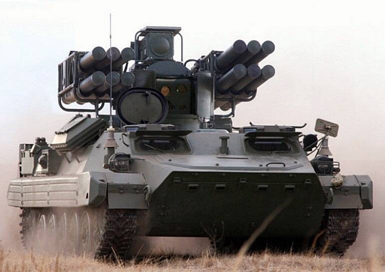
Complex on the landfill
As a further development of the existing complex, the Sosna system is a self-propelled combat vehicle with a full range of detection equipment and missile weapons. It is capable of carrying out air defense of formations on the march and in positions. Provides monitoring of the situation in the near zone with the possibility of the fastest possible attack and destruction of targets of various classes.
The manufacturer has announced the possibility of building the Sosna air defense system based on various chassis, the choice of which is the responsibility of the customer. Complexes for the Russian army are proposed to be built on the basis of MT-LB multipurpose armored vehicles. In this case, the combat module with the necessary equipment is mounted in the aft part of the roof, on the pursuit of the corresponding diameter. The use of such a chassis is not associated with serious difficulties, but at the same time it allows you to get some advantages. "Pine" on the basis of MT-LB can operate in the same battle formations with other modern armored vehicles, is able to overcome various obstacles and cross water barriers swim.

Optical-electronic equipment unit
The combat module of the "Pine" complex does not differ in its complex design. Its main element is a large vertical casing mounted on a flat turntable. It has all the necessary means of detection and identification, as well as missile launchers. The design of the module provides circular guidance of weapons and thereby simplifies monitoring the situation with subsequent firing.
In front of the combat module is a light armored casing with rectangular contours, which is necessary to protect the optoelectronic equipment unit. Before the start of combat work, the upper cover of the casing is folded back, and the side flaps are spread apart, which allows the use of optical instruments. On the roof of the module is the antenna for the radio command control system for the anti-aircraft missile. The sides of the module are equipped with mounts for two launchers. For preliminary guidance, the units are equipped with drives that are responsible for moving in the vertical plane.
A curious feature of the Sosna air defense system is the refusal to use radar detection equipment. It is proposed to monitor the air situation only with the help of optoelectronic systems. A combined missile control technique is also used, in which optical means play an important role.

Onboard electronics architecture
Observation, tracking and guidance tasks are assigned to the gyro-stabilized block of optical-electronic equipment. It includes a daytime camera and a thermal imager. A separate thermal imaging device is designed to track a rocket in flight. Three laser devices are installed on the unit: two are used as rangefinders, while the third is used as part of a missile control system.
The signal and data from the optoelectronic systems are fed to the main digital computing device and are displayed on the screen of the operator's console. The operator can observe the entire surrounding space, find targets and take them for escort. The operator is also responsible for launching the rocket. Further processes of aiming the product at the target are carried out automatically without human intervention.

In motion along the polygon
The Sosna air defense missile system uses the 9M340 Sosna-R anti-aircraft missile, developed on the basis of ammunition for existing systems. The rocket is characterized by reduced dimensions and has a combined control system. In this case, the product simultaneously carries two warheads different types, which allows you to significantly increase the likelihood of hitting the target.
With a maximum body diameter of 130 mm, the Sosna-R rocket is 2.32 m long and weighs only 30.6 kg. The rocket with a transport and launch container has a length of 2.4 m and a mass of 42 kg. In flight, the rocket is capable of speeds up to 875 m / s. It provides destruction of air targets at ranges up to 10 km and altitudes up to 5 km. The warhead of the rocket with a total mass of 7.2 kg is divided into an armor-piercing block, which is triggered by a direct hit on the target, and a rod-type fragmentation block. Undermining is carried out using a contact or laser remote fuse.

Preparing to shoot
The ammunition load of the Sosna combat vehicle includes 12 9M340 missiles in transport and launch containers. Six missiles (two rows of three) are placed on each airborne launcher. TPK anti-aircraft missiles are mounted on a large frame with vertical guidance drives connected to a gyroscopic stabilizer. A positive feature of the Sosna air defense missile system is the ability to reload without using a transport-charging vehicle. Relatively light missiles can be fed to the launcher by the crew. It takes about 10 minutes to recharge.
The use of a combined control system based on commands from the ground made it possible to optimize the design of the missile and obtain the maximum possible combat characteristics. Immediately after the launch, the rocket using the accelerating engine is controlled according to the radio command principle. With the help of commands from automatics coming from the antenna of the combat module, the rocket passes the initial phase of the flight and is displayed on a given trajectory. Further it is "caught" by the laser beam of the guidance system. Automation directs the beam to the calculated meeting point with the target, and the rocket is independently held on it throughout the entire flight. The warhead is detonated independently, at the command of one or another detonator.

Sosna-R missile launch
The developer declared the possibility of intercepting a variety of air targets that threaten troops on the march or in positions. The Sosna-R missile is capable of striking aircraft flying at speeds up to 300 m / s, cruise missiles at speeds up to 250 m / s and helicopters accelerating up to 100 m / s. At the same time, the real indicators of the maximum range and altitude vary slightly depending on the type and characteristics of the target.
According to the manufacturer, the newest domestic anti-aircraft complex "Sosna" is capable of carrying out air defense of formations or areas, working independently or as part of batteries. Observation of the airspace can be carried out on its own, however, it is possible to obtain third-party target designation from other detection means. The applied complex of optoelectronic equipment ensures all-weather and round-the-clock combat work with sufficient efficiency. Automation is capable of firing and hitting targets both when working in position and in motion.

Target engagement zones
SAM "Sosna" also has a number of other advantages directly related to the main ideas of the project in the field of surveillance equipment. The lack of radar surveillance equipment allows you to covertly monitor the situation and not unmask yourself with radiation. Observation in the optical and thermal ranges also allows you to actually get rid of the restrictions on the minimum altitude for target detection, tracking and attack. The rocket is guided using a laser beam, the receivers for which are located on its tail section. Thus, the complex is insensitive to means of optical or electronic suppression.
At the beginning of last year it became known that in the foreseeable future the promising anti-aircraft missile system "Sosna" will enter service and will be put into mass production. The recently published video, obviously targeting a foreign customer, demonstrates the developer's intention to obtain export contracts. Earlier there was information about the possible use of developments on the Sosna air defense system in new projects. So, it was argued that the promising airborne anti-aircraft complex "Ptitselov", intended for the Airborne Forces, will receive a combat module of the "Sosna" type with 9M340 missiles.
Previously, KB of Precision Engineering. A.E. Nudelman published various information about the Pine project. In addition, by now photographs of such a combat vehicle in various situations have become public knowledge. Now everyone has the opportunity to see the new anti-aircraft complex "in dynamics". A video published a few days ago shows how the Sosna air defense system behaves on the tracks of the training grounds, how it fires at air targets and what results such attacks lead to.
Based on materials from sites:
http://npovk.ru/
http://rbase.new-factoria.ru/
http://gurkhan.blogspot.ru/
https://bmpd.livejournal.com/
Self-propelled anti-aircraft missile system "KRUG"
The formation of requirements for the first air defense system of the Ground Forces "Circle" was characterized by the tendencies that determined the totality of the main characteristics of the first missile systems of the Air Defense Forces of the country - C-25 and C-75 and the necessary requirements of the Ground Forces in terms of cross-country capability, time of readiness for combat work from the march and the absence of wired communication lines and electrical cables between the facilities of the complex. High-speed and high-altitude targets were considered as the main ones, practically invulnerable to cannon anti-aircraft artillery and not always available for interception by front-line fighters.
Of course, the mobile version of the Krug air defense system did not allow to provide such a large engagement zone as the S-200 system of the Air Defense Forces, which began development in the summer of 1958. time for armament of the SA-75 "Dvina" air defense system, which ensures the destruction of targets flying at altitudes up to 22 km at a distance of up to 29 km, but also only its modernized version, the S-75M "Volkhov", planned for design, with a range of up to 40 km.
By the decree of the Central Committee of the CPSU and the Council of Ministers of the USSR of February 13, 1958 No. 2188-88 "On the creation of a prototype of the Krug anti-aircraft missile system" ) tests in the III quarter of 1961
The anti-aircraft missile system was intended to intercept targets flying at speeds up to 600 m / s at altitudes from 3000 m to 25000 m, at a distance of up to 45 km The probability of hitting a target such as a front-line Il-28 bomber at altitudes up to 20 km, one missile defense system should have been 0 , 8, while providing for the possibility of target maneuver with an overload of up to 4 units. A target with an effective scattering surface (EPR) corresponding to the MiG-15 fighter was supposed to be detected at a distance of 1 15 km, ensuring the deployment time from the march and the roll-off time - no more than 5 minutes.
The head organization for the development of the Krug anti-aircraft missile system (2K11) was designated NII-20 GKOT (director - PM Chudakov), chief designer - V.P. Efremov. The 1C32 missile guidance station of the Krug complex was developed at the same NII-20 by chief designer I.M. Drize, then - K.I. Popov.
The development of missiles on a competitive basis was entrusted to two artillery design bureaus, which had quite a lot of experience in creating anti-aircraft guns... The KS-40 (3M8) rocket weighing 1.8 tons with a ramjet engine was to be created by the OKB-8 team of the Sverdlovsk SNKh, headed by L.V. Lyuliev. The famous V.T. Grabin, chief designer of the TsNII-58 GKOT located in Kaliningrad near Moscow.
Grabin's work lasted for a relatively short time. The S-134 rocket designed by him was also equipped with a ramjet engine. In contrast to the Sverdlovsk sample, air was supplied to the combustion chamber through four sector air intakes. Grabinskaya firm independently developed the launcher under the designation C-135. In general, all this work was carried out for a little more than a year - on July 4, 1959, by Decree of the Central Committee of the CPSU and the Council of Ministers No. 739–338, TsNII-58 was attached to the nearby OKB-1 S.P. Queen. Grabin himself turned out to be not a lot, that is, teaching at the Moscow Higher Technical School. Most of his former employees, under the leadership of Korolev, began designing solid-propellant strategic ballistic missiles.
However, the competitive nature of the development remained. By the same Decree of July 4, 1959, OKB-2 of the State Committee for Aviation Technology (GKAT) of the chief designer P. D. Grushin was involved in the creation of missiles for the Krug, who proposed the B-757Kr missile for the Krug complex - a version of its B missile defense -757 ("product 17D") with a solid-fuel ramjet engine, developed in the same years for the country's Air Defense Forces. The Krug complex with the V-757Kr (ZM10) missile received the designation 2K11M and was to be submitted for joint tests at the end of 1960.
In addition to the "safety net" of the Sverdlovsk Design Bureau, the connection of OKB-2 pursued another goal - the implementation of the ever-living, but not always fruitful, idea of unifying rocket weapons. A number of complaints about the Grushinsky version of the rocket were made when considering its preliminary design in the summer of 1960. It was required to reduce the length and weight of the rocket. The specialists of the Ground Forces were not satisfied with the temperature range of operation and the permissible range of transportation of the starting engine, the operational characteristics of the radio fuse and the autopilot. It was necessary to abandon heating the ampoule battery and the main engine gas generator.
As already noted, the main developer of the 3M8 missile defense system, OKB-8, was unambiguously assigned the use of a ramjet engine (ramjet) on an anti-aircraft guided missile. The choice of this type of engine using non-aggressive liquid fuel seemed quite reasonable. Air oxygen was used as an oxidizer in the ramjet, so the rocket carried only fuel - kerosene. The ramjet engine surpassed rocket engines in terms of specific thrust by five or more times. For the rocket flight speeds, VZ-5 times higher than the sonic one, the ramjet engine was characterized by the lowest fuel consumption per unit of thrust even in comparison with the turbojet engine. Compared to it, the design of the ramjet engine was strikingly simple, and it was also much cheaper. Almost the only drawback of a ramjet was considered to be the inability to create significant thrust at subsonic speeds in the absence of the necessary high-speed pressure at the inlet to the air intake, which did not allow limiting the use of only ramjet on rockets launched from the ground.
In the mid-1950s. many attempts were made to introduce ramjet engines not only into rocket technology, but even into manned aircraft. "Ahead of the whole planet" here were the French. In addition to the obviously experimental aircraft of the Leduc company with more than extravagant placement in the central body of the air intake of the pilot's cockpit, piloting the aircraft in a piquant recumbent position, a real Griffin fighter with a combined turbo-ramjet engine was developed ...
In rocketry, in addition to many unrealized projects of products with ramjet engines, there were actually flying projectiles "Novakho" and serial anti-aircraft missiles "Bomark", "Super Bomark", "Bloodhound", "Teilos".
In our country, the greatest experience in the design and development of ramjet engines was accumulated in the SKB-670 GKAT by a team headed by chief designer M.M. Bondaryuk, back in the early 1950s. who developed such an engine for a rocket coastal complex"Storm". Their most significant work was the creation of a supersonic ramjet engine for an intercontinental cruise missile S.A. Lavochkin "Tempest", successfully worked out both at the stands and in flight tests. Development of engines for a similar rocket V.M. Myasishchev "Buran", as well as for other aircraft. True, the experience was somewhat one-sided - the engines were developed for low-maneuverable vehicles flying at a constant speed at practically the same altitude.
Taking into account the impossibility of ramjet operation at low speeds, the 3M8 rocket was made according to a two-stage scheme with the location of four starting engines according to a "batch" scheme. To ensure the conditions for starting a ramjet engine, solid-propellant boosters accelerated the rocket to a speed 1.5–2 times higher than the sound one.
By the end of the 1950s. there was already information about the unstable nature of the operation of ramjet engines at high angles of attack. On the other hand, an anti-aircraft missile designed to destroy highly maneuverable front-line aircraft required the implementation of transverse overloads of the order of 8 units. This largely determined the choice of the general rocket scheme. For the second (sustainer) stage, an arrangement with a rotary wing was adopted, which provided the ability to create a large lift at small angles of attack of the rocket body.
On the 3M8 rocket, it was initially provided for the use of combined control - a radio command system in the main flight section and homing in the final section of the SAM trajectory. The semi-active radar homing head was supposed to work on the signal reflected from the target by the pulse radiation signal of the target tracking channel of the missile guidance station.
The missiles were launched from the 2P24 self-propelled launcher (factory index KS-40), created in the same OKB-8, located on the "Object 123" tracked chassis developed by the Sverdlovsk Transport Engineering Plant on the basis of the "Object 105" chassis of the SU-100P self-propelled artillery mount. The artillery part of the launcher included a support beam with a boom hinged in its tail section and lifted by means of two hydraulic cylinders. On the sides of the boom were attached brackets with supports - "zero length" guides - to accommodate two missiles. At the start of the rocket, the front support swung down sharply, making way for the passage of the lower console of the rocket stabilizer. The missiles were launched at an angle of 10 ° to 55 ° to the horizon. Prior to that, on the march, the missiles were held by additional underwater supports, also attached to the boom. One support of the truss was brought in from the front and provided fixation of both missiles at once. Another support was advanced from the sides opposite to the arrow.
The height of the launcher with assembled missiles on the march exceeded 4 m, therefore, if necessary, the upper stabilizer console was removed under the overpasses.
The technical appearance of the rocket and the launcher was not formed immediately. At an early design stage, a variant of a rocket with a "+" -shaped arrangement of wings and an "x" -shaped tail was considered, while the launch of the missiles was envisaged from the beam guides of the launcher. Even after the start of flight tests, the possibility of switching from the frontal annular air intake to the side sector air intake was being worked out. In the process of development, the wingspan and tail slightly decreased.
An experimental SNR was mounted on a prototype self-propelled gun of the Baikal anti-aircraft self-propelled gun, which had not been adopted for service, on which the turret with anti-aircraft guns was replaced with an antenna post with a so-called “basket”, in which consoles and workplaces for three operators were placed. The "basket" was rotated in the azimuthal plane by ± 90 °. The antenna post, in turn, could turn around the "basket" by another ± 45 ° in azimuth and rise up to the vertical in elevation. However, this layout option turned out to be extremely cramped and inconvenient in operation - some of the devices were located even under the operator's seats. Counting and power supply devices were placed outside the "basket", in the building. The test results did not allow us to accept this layout scheme for further development, which was more suitable for a tank than for a radar - it was not possible to provide normal working conditions for the operators.
In the standard version, the missile guidance station was located on the object 124 self-propelled vehicle, basically similar to the launcher chassis. At the same time, the personnel and almost all instruments and assemblies were located in a fixed wheelhouse in the middle of the hull, and the rotary antenna post was in its stern.
Initially, all tests of the anti-aircraft missiles of the complex were supposed to be carried out at the Donguz test site in the Orenburg region, but it turned out to be too small given the required missile launch ranges. Therefore, in 1960, Kazakhstan began equipping a new landfill near the Emba railway station. The most necessary objects of this test site were prepared in 1963, which made it possible to conduct joint tests on it. The new facility was named the 11th State Test Site.
The initial plans provided for the delivery of telemetric missiles to the range in the 1st quarter. 1959, missile guidance stations - by June, and target detection stations - in the III quarter. the same year.
In fact, only on November 26, 1959, the first of 10 throw tests of a rocket mockup with full-scale starting engines took place, during which the first troubles were revealed - flutter, the destruction of the rocket during the separation of the start-ups ... Flight testing of the main engine with four missile launches without control equipment began in June 1960. Since August, without having achieved stable engine operation, they began to carry out programmed launches of missiles equipped with an autopilot, but without radio control equipment. Until June of next year, 32 such launches were completed. Of these, the first 16 missiles were equipped with a simplified autopilot, which did not provide roll control, and a turbo pump unit without a fuel consumption control device. Of the 26 launches carried out before the end of 1960, in six the rocket collapsed in flight, in seven the main engine did not turn on, and only 12 were relatively successful.
By the summer of 1960, the first tests of simplified versions of the Grushinskaya B-757 for the S-75 complex were carried out. Since January 23, three launches of prototypes have been performed, with a partially equipped gas generator, without rudders and destabilizers. In the course of these tests, the operation and separation of the accelerator, the operation of the main engine with the achievement of speeds from 560 to 690 m / s were checked. On April 22, autonomous tests of the rocket began, during which the developers of the B-757 encountered a number of difficulties.
Taking into account the delays in the development of missiles, by the Decision of the Military-Industrial Commission (MIC) under the Council of Ministers of the USSR No. 17 dated February 2, 1961, it was proposed to launch the B-750VN missiles of the C-75 complex with onboard equipment similar to adopted for the Krug air defense missile systems. On the basis of the 1SB7 airborne radio control and radio imaging unit from the 3M8 rocket, 20 sets of KRB-9 equipment were manufactured, suitable for placement on the V-750 family of missiles.
However, in August, it was not possible to switch to joint tests of the complex with a standard 3M8 rocket - by this time the first missile guidance station was still in the debugging stage, and the second sample was in the state of delivery of individual blocks. Nevertheless, on September 24, the first launch of the modified V-750VN rocket in a fixed beam SNR 1S32 took place. Depressing results showed the need for revision of the CHP.
During the first flight tests, the surge of the ramjet engine was also manifested, which worked satisfactorily only at low angles of attack. Due to the insufficient vibration resistance of the equipment, the surge led to a violation of the passage of commands and, as a result, to the loss of controllability of the missile defense system. At the 31st second, the transponder signal systematically disappeared. This mysterious phenomenon was overcome by moving the antenna from the rocket body to the stabilizer. Difficulties with the introduction of the rocket into the SNR beam were eliminated by spreading the installation of the range gate in time from the moment the accelerators were dropped. On the recommendation of the commission, the open-loop gain was reduced from 0.9 to 0.5, while the closed-loop gain was quadrupled. In 1961, the first 10 samples of 1SB7 were manufactured by the Tula plant "Arsenal".
Taking into account the large number of failures in the tests of 3M8 missiles, by the decision of the State Committee for Aviation Technology of August 25, 1961, a special expert commission was created to develop measures for the completion of the rocket. Most of the accidents were associated with burnouts of the combustion chamber, failures in the operation of the on-board equipment of the KRB, insufficient strength of a number of structural elements. A month later, on the recommendations of the commission, it was decided to change the design of the combustion stabilizers, eliminate the flow separation zones and increase the heat resistance of the combustion chamber of the main engine. Until the end of the year, it was planned to conduct additional firing tests of the engine at the CIAM stands, as well as vibration tests of the KRB equipment and the PT-10 on-board current converter - first autonomously, and then as part of a rocket.
In addition to the inoperability of the equipment under the influence of vibrations and undeveloped engines, the flight tests also revealed a discrepancy between the flight characteristics of the rocket and the specified ones. None of those made in 1960-1961. 55 launches failed to reach the maximum range. According to estimates, the specified level of maneuverability at high altitudes was not provided. NII-648 delayed the development of a prototype homing head (GOS) rocket. The onboard power supply was not completed.
By the end of 1961, the attitude of the military-industrial leadership to the B-757Kr missile had changed significantly. The deadline for completing work on the B-757 for the country's Air Defense Forces has been repeatedly postponed. Accordingly, the planned date for the start of flight tests of the B-757Kr for the Ground Forces also shifted to September 1962.
Prior to that, in the face of failures with the 3M8 SAM tests, Grushin's much greater experience in the creation of anti-aircraft missiles, in comparison with Lyuliev, contributed to the fact that the B-757Kr missile was already considered as the main version of the Krug missile system. The somewhat worse overall performance of this missile was to some extent compensated by interspecific unification with the B-757 missile ("product 17D"), developed for the S-75M air defense system of the country's Air Defense Forces. However, the ramjet engine turned out to be a "tough nut to crack" for the OKB-2 team as well. The development of the ramjet rocket was delayed, and already in 1960, the conventional liquid-propellant V-755 missile entered service with the S-75M air defense system - in fact, a thoroughly modified V-750VN missile. Without completing the development of the B-757 rocket, the Grushin residents began to work on a new missile with a ramjet - B-758 ("product 22D"). In these conditions, despite the failures with the 3M8, the 2K11M variant with the Grushin B-757Kr missile began to be regarded as secondary. In particular, by the decision of the military-industrial complex of December 28, 1961, it was instructed to consider the possibility of placing the V-757Kr missile on the standard 2P24 launcher instead of the 2P28 previously manufactured in one prototype, also designed on the SU-100P type chassis specifically for the Grushinsky missile. After the actual termination of the tests of the B-757 rocket, the decision of the military-industrial complex of October 17, 1962 raised the question of the expediency of further continuation of work on the B-757Kr rocket. Finally, work on the B-757 and B-757Kr was closed by the Decree of the Party and the Government of June 15, 1963.
In the fall of 1961, an experimental missile guidance station was installed instead of the experimental one. For her, as for the 2P24 launcher, it was envisaged to ensure tightness to protect against weapons of mass destruction.
However, the state of work on the Lyuliev rocket was also unfavorable, although in May 1962 factory tests of missiles with radio control equipment began. By the end of 1962, they did not achieve reliable operation of the onboard equipment of the KRB, did not determine the ballistic capabilities of the missile, did not manage to put into operation the second missile guidance station. On the other hand, there was also an encouraging result - an analysis of the capabilities of the missile guidance station and the dynamic characteristics of the missile defense system showed the possibility of ensuring acceptable accuracy when using only the radio command control system.
In 1962, a 3M8 rocket with a radio command system began to fly mostly without comment. By a decision of the military-industrial complex of January 12, 1963, the proposal of the GRAU and the industry was approved to conduct joint flight tests (SLI) in two stages - first only with the radio command system, then with the GOS. Thus, in fact, the process of abandoning the use of a combined guidance system on the rocket, including a semi-active seeker, began in favor of the purely radio command systems already mastered in the S-25, S-75 and S-125 air defense systems.
In the course of factory tests by April 1963, 26 launches were carried out. Most of them were carried out for the so-called electronic targets, two for parachute targets, four for the Il-28 converted into targets. In the process of joint tests from the beginning of 1963 to May, eight launches were carried out, of which three ended in failure. There was not a single successful missile launch at an elevation angle of the guides of more than 46 °, while it was required to ensure the possibility of launching at angles up to 60 °.
Of the 25 launches carried out from February to August 1963, only seven were able to shoot down targets - the Il-28. "Organizational conclusions" were being prepared, but the main shortcomings had already been revealed, and by the end of the year it was possible to successfully carry out a couple more launches. And this despite the fact that the missiles arrived at the test site out of time - only 21 of the required 40 missiles were delivered, slowly - over three weeks - the test results were processed. The ground facilities of the complex were not brought to the full complement - the vehicles were not equipped with navigation, orientation and topographic equipment, telecode communication systems. Gas turbine installations of machine power supply systems often failed. Only on the second launcher was the soundproofing system brought to a state that would ensure the possibility of a safe launch when the personnel were inside the 2P24. During the tests, there was a case, fortunately, which did not entail tragic consequences, instead of firing fighters that accompanied the target for its elimination in the event of missile defense missiles.

Launcher 2P24 with 3M8 SAM "Krug"
By the beginning of the next year, two more launches were carried out, both successful. However, none of the firing performed has yet been carried out with relatively small targets such as the MiG-17 and at targets flying at altitudes less than 3000 m. The missile's main engine still worked unstable at low altitudes. Self-oscillations occurred in the control loop, leading to unacceptable misses when flying over the target. The effectiveness of the radio fuse and the warhead on real targets was in doubt.
The difficulties associated with the creation of Krug missiles are characterized by the testimony of Igor Fedorovich Golubeev, deputy chief designer of Lyuliev.
“We took up the 3M8 SAM without fully realizing the complexity and difficulties of this work. ...
In 3M8, as you know, due to the lack of a suitable solid fuel with a good unit impulse in the country, it was decided to use a ramjet engine running on liquid fuel - kerosene. The ramjet engine was invented in 1903 by the Frenchman Legendre and since then it has been one of the most energy-efficient rocket engines, allowing you not to carry stocks of oxidizer on board.
But everything works well if the proportional air flow in relation to fuel is observed - about 15: 1. If this ratio changes, then the engine starts to be capricious and can stall or pump up. Therefore, one of the complex elements is the inlet diffuser and the fuel pump with injectors. Suffice it to say that it was necessary to "anneal" about ten thousand injectors before it was found optimal shape... And this is only for this type of engine, and in the event of a change in its geometric dimensions, everything would have to be repeated anew. This is one of the reasons why ramjet engines are not widely used now - they are unique in their specific performance. Each step during the development was given with difficulty and was solved literally from scratch.
From the beginning of controlled flights, the fight against attenuation of the signal of the on-board radio responder in the engine exhaust torch began. It turned out that the combustion products of ordinary kerosene shielded the transponder antenna very well. I had to take it to the tail console. As soon as we dealt with this, the rocket began to swing approximately in the middle of the flight trajectory and, with a frequency of 50:50, it passed this section, then lost control. The solution was simple - they mixed up the phases of the power supply to the gyroscopes of the SAM autopilot. Gyroscopes, after prelaunch spinning in the wrong direction, with the transition to onboard power, first began to slow down, stopped approximately in the middle of the trajectory, and then spun in the opposite direction again. If everything went well, then the further flight continued steadily. "
In general, during joint tests from February 1963 to June 1964, 41 missiles were launched, including 24 missiles in combat configuration. Four cases of wing flutter required the introduction of anti-flutter balancers, three "poor" breakdowns of the combustion process - modification of the fuel supply regulator, six explosions of isopropyl nitrate - improvement of the fuel system, two radio fuses failures - modification of its scheme.
But since the launches were mostly successful at the final stage of testing, the State Commission chaired by A.G. Burykina recommended the complex for adoption.
The corresponding Resolution of the Central Committee of the CPSU and the Council of Ministers of the USSR of October 26, 1964 - "On the adoption of the mobile anti-aircraft guided missile system" Krug "with SAM 3M8" determined the main characteristics of the complex. Most of the requirements for the main characteristics set by the 1958 Decree have been met. The exception was the range of flight altitudes of the targets hit - 3-23.5 km - 1.5 km did not reach the required maximum reach in height. The range of the engagement ranges was 11–45 km, the maximum heading parameter (the distance of the target path from the position of the air defense missile system in the lateral direction) was 18 km. For the permissible maximum target speed - up to 800 m / s - the original requirements were exceeded by 200 m / s. The detection range of an object with an EPR corresponding to the MiG-15 was 115 km. A typical target - an F-4C or F-105D fighter-bomber - was hit with a probability of 0.7. The reaction time of the complex was 60 s.

The layout of the 3M8 SAM "Circle"
1 - fairing: 2 - warhead: 3 - radio fuse: 4 - air pressure accumulator: 5 - fuel tanks: 6 - rotary wing; 7 - steering gear; 8 - radio control equipment: 9 - autopilot / 10 - isopropyl nitrate tank: 11 - starting booster: 12 - turbopump unit; 13 - nozzle block: 14 - combustion stabilizer: 15 - stabilizer

Starting engines ZTs5 on the 3M8 missile of the Krug air defense missile system
The 3M8 rocket was made according to a two-stage scheme. The body of the main stage of the rocket was a supersonic ramjet engine ZTs4 - a pipe with a pointed central body, sharp leading edges of the frontal air intake, annular nozzles and combustion stabilizers. On previous missiles of similar schemes, most of the systems and assemblies were placed in a ring scheme in the outer housing of the ramjet engine. However, for a number of elements, for example, the warhead, such a location was clearly contraindicated. In the central body of the air intake with a cylindrical part of 450 mm in diameter, in addition to the high-explosive fragmentation warhead ZN11 weighing about 150 kg, there was a radio fuse ZE26 and a ball cylinder for an air pressure accumulator. In front of the central body, it was supposed to install a homing head. The central body was slightly recessed into the inner volume of the rocket body. Further, there were openwork structures made of annular and radial elements - straightening grids, nozzle blocks, combustion stabilizers. In the annular engine casing with an outer diameter of 850 mm, starting from its leading edge, there were tanks with kerosene, approximately in the middle of the length - steering gears, wing attachments, and closer to the trailing edge - control system (CS) equipment blocks.
Swivel wings with a span of 2206 mm were placed according to the "X" -shaped scheme and could be deflected by the hydropneumatic steering drive in the range of ± 28 °. The wing chord was 840 mm at the base, 500 mm at the tip. The sweep along the leading edge was 19 ° 38 along the trailing edge - 8 ° 26 '(negative), the total area in one plane of the turning parts of both consoles was 0.904 m2.
Stabilizers with a span of 2702 mm were installed according to the "+" - shaped scheme. Chord 860 mm at the base, 490 mm at the tip. The leading edge is swept 20 °, the trailing edge is straight, the total area of two consoles in one plane is 1.22 m2. The length of the rocket was 8436 mm, the diameter was 850 mm.
With a starting weight of 2455 kg, the initial weight of the second (sustainer) stage was about 1400 kg, of which about 270 kg were fuel - kerosene T-1 (or TS) and 27 kg - isopropyl nitrate.
The fuel supply was provided by a C5.15 turbo pump unit (on the first samples - C2.727), operating on a monofuel - isopropyl nitrate. This unitary fuel, in comparison with hydrogen peroxide, which was previously widely used in rocket technology, at a slightly lower density (by about a quarter) had more energy and, more importantly, was more stable and safer in operation.
Each of the four starting engines ZTs5 was equipped with a charge of ^ 11 solid baplistite fuel RSI-12K weighing 173 kg in the form of a single-channel checker 2635 mm long with an outer diameter of 248 mm and a channel diameter of 85 mm. To ensure the separation of the starting engines from the sustainer stage, a pair of small aerodynamic surfaces was fixed on each of them in the stern bow.
For radio command control of the SAM flight under the direction of R.S. Tolmachev, a missile guidance station (CHR) 1C32 was developed, which was a coherent-pulse centimeter-range radar. The station's antenna post was a rather complex rotary structure with several dish antennas, the largest element of which was the target channel antenna. To the left of it was the antenna of the narrow beam of the rocket channel, above which the antennas of the wide beam of the rocket channel and, closer to the periphery, the transmitter of commands to the rocket were located. Later in the upper part of the antenna post, a camera of a television-optical sight was placed. The station automatically processed the target designation information received via the telecode from the target detection station (SOC) 1С12, and made a quick target search. The search was required to be conducted only in elevation, since the resolution of the target detection station in the vertical plane was much worse than in the horizontal one. After the target was detected, it was captured for auto-tracking in angular coordinates and range.
Further, the calculating device at the missile guidance station determined the boundaries of the launch and defeat zones, the angles of installation of the antennas for the capture and tracking of missiles (with wide and narrow scanning beams), as well as the data entered into the target and missile auto range finder. By telecode commands from the missile guidance station, the launcher was turned in the direction of launch. After the target entered the launch zone and the command transmitter was turned on, the launch was carried out by pressing a button at the missile guidance station. According to the signals of the on-board transponder, the missile defense system was captured for tracking by the goniometric (with a wide beam) and rangefinder channels of the missile guidance station and was first introduced into the narrow beam of the missile channel antenna, which was then set parallel to the target channel antenna. On board the rocket, flight control commands were transmitted, formed by the calculating device of the missile guidance station, as well as a one-time command to remove the radio fuse from the protection.
The aiming of the missile defense system was carried out by the "half-straightening" method or by the "three-point" method. The radio fuse was triggered when the missile flew at a distance of less than 50 m from the target. Otherwise, the rocket self-destructed.
In station 1C32, a method of hidden monoconic scanning along angular coordinates was implemented and an electronic self-rangefinder of the target was used. Resistance from passive, range-shifting, response and asynchronous interference was ensured by tuning in frequency and lettering of channels, high energy potential of the transmitter, selection of signals by amplitude, the possibility of simultaneous operation with one missile defense system at two frequencies, as well as coding of control commands.

Radar guidance of missiles 1S32 SAM "Krug" and its scheme

1S32 missile guidance radar in combat position

Target detection radar 1S12 SAM "Krug"

In accordance with the calculated characteristics, the pulsed power of the missile guidance station was 750 kW, the receiver sensitivity was 10 -13 W, and the beam width was 1 °. Target capture for auto-tracking in a noise-free environment could be carried out at a distance of up to 105 km. At a given level of interference (1.5-2 packs of dipoles per 100 m of the target path), the auto-tracking range was reduced to 70 km.
Target tracking errors in angular coordinates did not exceed 0.3 d.u., in range - 15 m. In the future, intermittent modes of operation and auto-tracking using a television-optical sight were introduced to protect against Shrike-type missiles.
It is known that in the S-75 air defense system, the main combat unit - the anti-aircraft missile division - had the ability to independently conduct hostilities, having in its composition, along with missile guidance stations, target reconnaissance means - usually radars of the P-12 family, often in combination with altimeters.
The anti-aircraft missile battalion, armed with the Krug air defense system, also included a target reconnaissance facility, the role of which was played by the 1C12 target detection station - a centimeter-range rangefinder radar. In combination with one or two PRV-9A radio altimeters, the same radar under the name P-40 ("Armor") was also used in the radar companies of the military air defense. The radar was developed by NII-208 (later NII IP of the Ministry of Radio Industry) under the leadership of the chief designer V.V. Reisberg.
The 1C12 target detection station provided fighter detection at ranges of up to 180 km (at a flight altitude of 12,000 m) and 70 km for a target flying at an altitude of 500 m. 3-7.7x10 -14 watts. In a circular view, four beams were sequentially formed in the elevation plane: two lower beams with a width of 2 ° and 4 °, and also two upper ones with a width of 10 ° and 14 °. The beam direction was switched electromechanically.
As a self-propelled vehicle for the station 1C12 was adopted chassis "object 426", developed in the design bureau of the Kharkov plant of transport engineering named after. V.A. Malyshev on the basis of the AT-T heavy artillery tractor created there. In terms of a number of indicators, including security, it was inferior to the chassis based on the SU-100P. The diversity of tracked vehicles in the anti-aircraft missile battalion did not bode well either. In this case, the choice of the chassis was determined by the mass of the equipment and antenna post of the 1C12 station, which is twice as large as compared to the missile guidance station.
The most important advantage of the combat assets of the anti-aircraft missile battalion was the autonomy of their power supply, provided by built-in gas turbine units with a capacity of 40 to 120 hp. Information exchange between the division's facilities was provided by radiotelecode communication. For the first time, gyroscopic navigation and topographic control devices were installed in the air defense missile systems. The presence of these means and the elimination of cable connections made it possible to drastically reduce the time spent on their deployment-folding in a combat position.

Target detection radar 1S123RK "Circle" (in the stowed position) and its diagram

As already noted, the main subdivision of the Krug complex was an anti-aircraft missile division, which included a command platoon, three anti-aircraft missile batteries, each of which included one 1C32 missile guidance station and three 2P24 launchers with paired guides, as well as a technical battery. Thus, the division included three missile guidance stations and nine launchers with 18 combat-ready missiles.
The control platoon housed the 1C12 target detection station, as well as the target designation cabin of the Crab combat control complex (K-1).
The technical battery consisted of 2V9 control and testing stations, 2T6 transport and charging machines, 9T25 transport vehicles, refueling vehicles, as well as technological equipment for assembling and refueling missiles with fuel.
In essence, the anti-aircraft missile division formed the anti-aircraft missile system as the minimum combination of forces and means that ensure the detection and defeat of an air target.
Despite the possibility of conducting independent hostilities, the own means of the anti-aircraft missile battalion did not provide the most efficient use its combat potential. This was determined, first of all, by the limited search capabilities of the 1C12 station, taking into account its placement on the real terrain with shaded zones, as well as the extremely short flight time when enemy aircraft operated at extremely low altitudes.
To ensure a more effective use of anti-aircraft missile divisions, they were included in anti-aircraft missile brigades with unified system management.
The brigade, designed to solve the air defense tasks of the front (army), along with three anti-aircraft missile divisions, included a control battery. The command battery of the brigade contained a combat control cabin of the "Crab" complex, as well as its own means of detecting air targets - detection radars P-40D, P-18, P-19, radio altimeter PRV-9A (or PRV-11).
The joint work of the command posts of the brigade and divisions was ensured by the command complex K-1 ("Crab"). It was created in 1957-1960. by the OKB-563 GKRE team under the leadership of the chief designer B.C. Semenikhin. Initially, the "Crab" complex, which later received the index 9C44, was intended for automated control anti-aircraft fire artillery regiment, armed with S-60 automatic cannons, but was then brought up to support the combat operation of the S-75 anti-aircraft missile regiment.
In addition to the command post of the brigade - a combat control cabin, located on the Ural-375 chassis, and command posts of divisions - target-indicating reception booths (on the ZIL-157), the complex included a narrow-band transmission line for radar images "Setka-2K", a GAZ- 69T and power supplies in the form of separate diesel power plants.
The complex allowed on the spot and in motion to visually display the air situation on the brigade commander's console according to information from the P-10, P-12 (P-18), P-15 (P-19) and P-40 radars. When targets were found at a distance of 15 to 160 km, up to 10 targets were simultaneously processed, target designations were issued with forced guidance of the antennas of the battery missile guidance station in specified directions, and the acceptance of these target designations was checked. The coordinates of the 10 targets selected by the brigade commander were entered into the computer by two data retrieval operators, after which the information was transmitted directly to the battery missile guidance station.
The working time of the K-1 complex from the detection of an enemy aircraft to the issuance of target designation to the division, taking into account the distribution of targets and the possible need to transfer fire, was 32 s. The reliability of target designation development reached more than 90% with an average target search time by the missile guidance station of 15–45 s.
In addition, the complex made it possible to receive at the command post of the brigade and relay information about two targets coming from the command post of the air defense of the front (army).
By Decree No. 966-379 of October 26, 1964, the cooperation of the main manufacturers of the elements of the complex was also determined. Serial production of the 1C12 detection stations was carried out at the Lianozovsky electromechanical plant MRP, and the 1C32 missile guidance stations at the Mari machine-building plant MRP. 2P24 launchers and missiles were produced at the Sverdlovsk Machine-Building Plant named after I. M.I. Kalinina MAP. Nearby, at the Sverdlovsk plant of electroautomatics, serial production of the K-1 "Crab" control complex was in progress.
As usual in government decrees, along with the adoption of the complex for the armament of the industry, work was asked to further improve it, which was carried out in several stages.
First of all, improvements were made to reduce the lower reach and reduce the "dead zone".
To hit low-flying targets, they switched to shooting with an excess, which excluded premature detonation of the fuse. The SNR equipment was improved - two launch zones were displayed on the screen, corresponding to firing at maneuvering or low-maneuverable targets. To increase the likelihood of hitting maneuvering targets, a nonlinear corrector was added to the control loop, and the open loop gain value was returned to 0.9. For the use of air defense systems in conditions of the threat of the use of anti-radar missiles, a television-optical sight was used.
In 1967, the Krug-A air defense missile system was adopted, for which the lower border of the affected area was reduced from 3 to 0.25 km, and the near border was brought closer from 11 to 9 km.
After the modifications carried out, the rocket as an aircraft in 1971 was adopted by the Krug-M air defense system. The far border of the affected area of the complex was removed from 45 to 50 km, the upper one was raised from 23.5 to 24.5 km.
In 1974, the Krug-M1 was adopted, for which the lower border was lowered from 0.25 to 0.15 km, and the near border was reduced from 11 to 6-7 km. It became possible to defeat targets on catch-up courses at a distance of up to 20 km.
Further expansion of the capabilities of the Krug complex was associated with the improvement of its combat control facilities.
The "Crab" complex was originally developed mainly in order to ensure the control of the combat actions of anti-aircraft artillery units and when used as part of the brigades of the "Krug" complex, it had a number of disadvantages:
A mixed control mode was not provided (the most effective in a real combat situation);
There were significant restrictions on target designation capabilities (one target was issued instead of the required 3-4);
Information from divisions about independently chosen targets could not be transmitted to the brigade's command post;
The brigade command post was technically interfaced with the higher air defense units (front and army air defense command posts) only using radiotelephone channels and a tablet data exchange scheme, which led to an average delay of 40 s and the loss of up to 70% of targets;
The battalion command post, when receiving information from its own 1C12 target detection station, delayed the passage of target designation to the batteries and lost up to 30% of targets;
The range of radio links was insufficient, amounting to 15–20 km instead of the required 30–35 km;
The complex used only a telecode communication line between the command posts of the brigade and divisions with insufficient noise immunity.
As a result, the fire capabilities of the Krug brigade were used only by 60%, and the degree of participation of the brigade's command post in organizing the repelling of the raid was less than half of the fired targets.

Scheme of the 2P24 launcher for the Krug air defense system

Transport vehicle 9T25 of the Krug complex

Transport-loading vehicle 2T6 of the Krug complex
In accordance with the Decree of April 14, 1975, a automated system control (ACS) of combat operations of the anti-aircraft missile brigade "Krug" - "Polyana D-1" (9S468M1). The development was carried out by the Research Institute of Automatic Equipment (Research Institute AA) of the Ministry of Radio Industry, chief designer - S.M. Chudinov.
The command post of the brigade (PBU-B) 9S478 included a 9S486 combat control cabin, a 9S487 interface cabin and two diesel power plants.
The battalion's command post (PBU-D) 9S479 consisted of a 9S489 command and control cabin and a diesel power plant.
In addition, the automated control system included a 9C488 maintenance cab.
All cabins and power plants PBU-B and PBU-D were located on the chassis of Urap-375 vehicles with a unified K1-375 van body. An exception was the UAZ-452T-2 topographic surveyor as part of the brigade PBU (PBU-D topographic location was provided by the appropriate means of the division). Communication between the front (army) air defense command post and PBU-B, between PBU-B and PBU-D was carried out via telecode and radiotelephone channels.
PBU-B were attached to radars (P-40D, P-18, P-19, PRV-16, PRV-9A) operating in different frequency ranges and having cable connections with PBU-B.
PBU-B in automatic mode ensured the distribution of targets between divisions, setting fire missions to them and coordinating their firing at targets, as well as receiving commands and targeting from higher command posts and transmitting reports to them.
PBU-B technical means provided:
Reception of information from the radar and its display on a scale of 150 km and 300 km, remote control of equipment for determining the nationality of targets, as well as automated reception of information about the height of targets from PRV-16 (PRV-9A) radio altimeters with the issuance of target designations (TS) to these altimeters ;
Semi-automatic acquisition of coordinates and processing of up to 10 target traces;
Reception from higher command posts and displaying information on 20 targets, working out target designations issued by them for 2 targets, as well as generating and transmitting information about the brigade's combat operations to higher command posts;
Reception and display of information from PBU-D about the targets selected for shelling and for subsequent firing cycles (4 targets per battalion), as well as the position, condition, combat readiness and results of combat operations of the battalion and its batteries;

Interface and communication cabin 9S487 (KSS-B) of the 9S478 (PBU-B) combat command post of the Krug anti-aircraft missile brigade - 9S468M1 ACS

The 9S486 (KBU-B) combat control cabin of the 9S478 (PBU-B) combat control unit of the Krug anti-aircraft missile brigade - ASU9S468M1 (Polyana-D1)

Combat control cabin (right) 9S489 (KBU-D) and power plant (left) of the 9S479 combat control point (PBU-D) of the Krug anti-aircraft missile battalion - ASU 9S468M1 (Polyana-D 1)
the authorDIVISION SELF-PROPELLED ANTI-AIR MISSION COMPLEX "KUB" The development of a self-propelled anti-aircraft missile system "Kub" (2K12), designed to protect troops, mainly tank divisions, from air attack weapons flying at medium and low altitudes, was assigned
From the book Technique and armament 2003 07 the author Technics and Armament Magazine From the book Technique and armament 2014 01 authorDIVISIONAL AUTONOMOUS SELF-PROPELLED ANTI-AIR MISSION COMPLEX "OSA" Development of an autonomous self-propelled military anti-aircraft missile system "Osa" (9K33) 1 * began in accordance with the Resolution of the Council of Ministers of the USSR dated October 27, 1960. The complex was intended to destroy targets,
From the author's bookSelf-propelled anti-aircraft missile system "KUB" Unlike the "Krug" air defense missile system, the "Kub" complex was originally created specifically to defeat mainly low-flying targets, that is, to solve the tasks most characteristic of countering front-line aviation. Wherein
From the author's book From the author's bookDivisional self-propelled self-propelled anti-aircraft missile system "OSA" Anti-aircraft missile system "Cub" was intended to cover from air strikes primarily tank divisions of the Ground Forces.
From the author's book From the author's bookRegimental self-propelled anti-aircraft missile system "Strela-1" information on the development in the United States of a wearable air defense missile system equipped with a passive thermal homing missile, which later received the name "Red Eye", the Soviet military
From the author's bookRegimental self-propelled anti-aircraft missile system Strela-10 With the creation of the Strela-1 air defense system, it became possible to form in regimental anti-aircraft divisions rocket and artillery batteries, consisting of a platoon with four missile systems and a platoon of four Shiloks, which
From the author's bookAnti-aircraft missile system M-22 "Uragan" Rostislav Angelsky, Vladimir Korovin In the late 1960s. the basis of the air defense of the domestic fleet was two shipborne air defense systems - the M-1 "Volna" and the M-11 "Storm" that replaces it (for the M-1 and M-11 complexes, see T&V No. 11.12 / 2013. ). Both