USB (Universal Serial Bus- "universal serial bus") - a serial data interface for medium-speed and low-speed peripheral devices. A 4-wire cable is used for connection, while two wires are used for receiving and transmitting data, and 2 wires are used to power the peripheral device. Thanks to built-in USB power lines allows you to connect peripherals without their own power supply.
USB Basics
USB cable consists of 4 copper conductors - 2 power conductors and 2 data conductors in twisted pair, and a grounded braid (screen).USB cables have physically different "to device" and "to host" tips. It is possible to implement a USB device without a cable, with a tip "to the host" built into the case. It is also possible to permanently embed the cable in the device(e.g. USB keyboard, Webcam, USB mouse), although the standard forbids this for full and high speed devices.
USB bus it is strictly oriented, i.e. it has the concept of “main device” (host, also known as a USB controller, usually built into the south bridge chip on the motherboard) and “peripheral devices”.
Devices can be powered by +5 V from the bus, but may also require an external power supply. The standby mode is also supported for devices and splitters on command from the bus with the removal of the main power supply while maintaining the standby power and switching on at the command from the bus.
USB supportshot plugging and unplugging devices. This is possible due to the increase in the length of the conductor of the grounding contact in relation to the signal. When connecting USB connector close first ground contacts, the potentials of the cases of the two devices become equal and further connection of the signal conductors does not lead to overvoltages, even if the devices are powered from different phases of the three-phase power network.
At the logical level, a USB device supports data transfer and receive transactions. Each packet of each transaction contains a number endpoint on the device. When a device is connected, drivers in the OS kernel read the list of endpoints from the device and create control data structures to communicate with each endpoint of the device. The set of endpoints and data structures in the OS kernel is called channel (pipe).
Endpoints, and hence the channels, belong to one of 4 classes:
- flow (bulk),
- manager (control),
- isochronous (isoch),
- interrupt.
Low speed devices such as a mouse cannot be isochronous and flow channels.
Control channel designed to exchange with the device short packets "question-answer". Any device has control channel 0, which allows the OS software to read brief information about the device, including manufacturer and model codes used to select a driver, and a list of other endpoints.
Interrupt channel allows you to deliver short packets in both directions, without receiving a response / confirmation to them, but with a guarantee of delivery time - the packet will be delivered no later than in N milliseconds. For example, it is used in input devices (keyboards, mice or joysticks).
Isochronous channel allows packets to be delivered without a guarantee of delivery and without responses/acknowledgments, but with a guaranteed delivery rate of N packets per bus period (1 kHz for low and full speed, 8 kHz for high speed). Used to transmit audio and video information.
Stream channel provides a guarantee of delivery of each packet, supports automatic suspension of data transfer at the device's unwillingness (buffer overflow or underflow), but does not guarantee the speed and delay of delivery. Used, for example, in printers and scanners.
bus time is divided into periods, at the beginning of the period, the controller sends the “beginning of period” packet to the entire bus. Further, during the period, interrupt packets are transmitted, then isochronous in the required amount, in the remaining time in the period, control packets are transmitted, and lastly, stream packets.
Bus active side is always the controller, the transmission of a data packet from device to controller is implemented as a short question from the controller and a long, data-containing response from the device. The packet movement schedule for each bus period is created by the joint effort of the controller hardware and driver software; for this, many controllers use DMA direct memory access (Direct Memory Access) - data exchange mode between devices or between the device and the main memory, without the participation of the Central Processor (CPU). As a result, the transfer speed is increased because data is not sent to and from the CPU.
The packet size for the endpoint is a constant hardcoded into the endpoint table of the device and cannot be changed. It is selected by the device developer from among those supported by the USB standard.
USB specifications
Features, advantages and disadvantages of USB:
- High exchange rate (full-speed signaling bit rate) - 12 Mb/s;
- Maximum cable length for high exchange rate - 5 m;
- Low exchange rate (low-speed signaling bit rate) - 1.5 Mb / s;
- Maximum cable length for low baud rate - 3 m;
- Maximum connected devices (including multipliers) - 127;
- It is possible to connect devices with different exchange rates;
- No need to install additional items such as terminators;
- Supply voltage for peripheral devices - 5 V;
- The maximum current consumption per device is 500 mA.
USB signals are transmitted over two wires of a shielded 4-wire cable.
USB 1.0 and USB 2.0 connector pinout
| Type A | Type B | ||
| Fork (on cable) |
Power socket (on the computer) |
Fork (on cable) |
Power socket (on the peripheral device) |
 |
|||
Names and Functions of USB 1.0 and USB 2.0 Pins
Disadvantages of USB 2.0
Though the maximum USB 2.0 transfer rate is 480 Mbps (60 Mbps), in real life it is unrealistic to achieve such speeds (~ 33.5 Mbps in practice). This is due to the large delays of the USB bus between the request for data transfer and the actual start of the transfer. For example, the FireWire bus, although it has a lower peak bandwidth of 400 Mbps, which is 80 Mbps (10 MB / s) less than USB 2.0, in reality allows for more bandwidth for communicating with hard drives and other storage devices. In this regard, a variety of mobile drives have long "rested" against the insufficient practical bandwidth of USB 2.0.
Sent by:
Viktor Pankov sent an interesting link to an article that describes in detail the features of the pinout of USB connectors for the correct charging of various gadgets, because it's no secret that gadgets often refuse to charge from a simple USB port of a drive or computer, or behave differently than we would like.
Most modern gadgets (mobile phones, smartphones, players, e-books, tablets, etc.) support charging via the USB mini/micro socket. There may be several connection options:
The device can be charged from a PC via a standard data cable. Usually this is the USB_AM-USB_BM_mini/micro cable. If the device requires more than 0.5A of current to charge (which is the maximum that USB 2.0 is capable of), then the charge time can be painfully long, up to infinity. The USB 3.0 port (such a blue one) already gives out 0.9 A, but even this may not seem enough to someone.
Through the same data cable, your device can be charged from a native charger (network or car) equipped with a 4-pin USB-AF socket, like on a computer. Of course, this is no longer a real USB port. The charger socket only outputs approximately 5V between pins 1 and 4 of the 4-pin socket (positive on pin #1, minus on pin #4). Well, all sorts of jumpers and resistors can be installed between the different contacts of the socket. What for? This witchcraft will be discussed below.
The gadget can be connected to a third-party or homemade charger that provides 5 volts. And this is where the fun begins...
When you try to charge from someone else's charger with a USB output, your gadget may refuse to charge under the pretext that the charger allegedly does not suit it. The answer is that many phones / smartphones “look” how the Data + and Data- wires are disconnected, and if the gadget doesn’t like something, this memory will be rejected.
Nokia, Philips, LG, Samsung, HTC and many other phones will only recognize the charger if the Data+ and Data- pins (2nd and 3rd) are shorted. You can short-circuit them in the USB_AF socket of the charger and safely charge your phone through a standard data cable.

If the charger already has an output cord (instead of an output jack) and you need to solder a mini/micro USB plug to it, don't forget to connect pins 2 and 3 in the mini/micro USB itself. At the same time, you solder plus on 1 contact, and minus - on the 5th (last).

At iPhones in general, some occult requirements for switching the charger socket: the Data + (2) and Data- (3) contacts must be connected to the GND contact (4) through 49.9 kΩ resistors, and to the + 5V contact through 75 kΩ resistors.

Motorola"requires" a 200 kΩ resistor between the 4 and 5 pins of the USB micro-BM plug. Without a resistor, the device does not charge until complete victory.

For charge samsung galaxy The USB micro-BM plug must have a 200 kΩ resistor between pins 4 and 5 and a jumper between pins 2 and 3.

For a more complete and "humane" tablet charge Samsung Galaxy Tab recommend another circuit: two resistors: 33 kΩ between +5 and jumper D-D+; 10 kΩ between GND and jumper D-D+.

Apparatus e-ten("Raccoon") is not interested in the state of these contacts, and will support even a simple charger. But he has an interesting requirement for the charging cable - "Raccoon" is charged only if pins 4 and 5 are shorted in the mini-USB plug.

If you don’t want to mess with a soldering iron, you can buy a USB-OTG cable - it has pins 4 and 5 already closed in the mini-USB plug. But then you still need a USB AM-AM adapter, that is, “dad” - “dad”.

The Ginzzu GR-4415U car charger, which claims to be universal, and its analogues are equipped with two output sockets: HTC / Samsung and Apple or iPhone. The pinout of these sockets is shown below.

A special data cable is required to power or charge your Garmin navigator. Just to power the navigator through the data cable, you need to short-circuit pins 4 and 5 in the mini-USB plug. For recharging, you need to connect 4 and 5 pins through an 18 kOhm resistor:

So, if you want to convert a regular memory into a USB charger for your phone:
Make sure the device is putting out about 5 volts DC.
Find out if this charger can provide a current of at least 500 mA
Make the necessary changes to the wiring of the USB-AF socket or USB-mini/micro plug
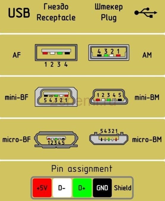
USB (Universal Serial Bus - Universal Serial Bus) The whole variety of USB version 2.0 connectors is shown in the picture below. The picture is clickable.
For the avoidance of doubt: In all tables, the view of the connector is given from its external, working side (and not from the mounting side!), unless otherwise specified. The insulating parts of the connector are marked in light grey, the metal parts are marked in dark grey, and the connector cavities are marked in white.
Well, a simplified, so to speak, practical scheme:


The name of this or that connector is supplied with letter indices.
connector type:
- A - active, powering device (computer, host)
- B - passive, connected device (printer, scanner)
"Gender" of the connector:
- M (male) - plug, "dad"
- F (female) - nest, "mother"
Connector size:
For example: USB micro-BM-plug (M) for connecting to a passive device (B); micro size.
USB connector pinout (jacks and plugs)
The purpose of the wires in the USB cable is as follows:
- Red VBUS (+5V, Vcc - Voltage Collector Collector) +5 volts DC voltage with respect to GND. Maximum current - 500 mA
- White D-(-Data)
- Green D+ (+Data)
- Black GND - common wire, "ground", "minus", 0 Volt
The mini and micro connectors contain 5 pins:
- Red VBUS
- White D-
- Green D+
- ID - not used in connectors "B"; in connectors "A" shorted to GND to support the "OTG" function
- Black GND
Among other things, the cable contains (though not always) a bare Shield wire - a case, a screen, a braid. This wire is not assigned a number.
Good news
A reversible micro-USB plug is announced on the Internet, which, like USB 3.1 Type-C, does not require a clear orientation of ± 180 ° when connected to the socket.

Mouse and Keyboard Cord Pinout
Some mice and keyboards may have cable colors that are different from the standard. Detailed article on custom colors: "USB custom colors in mouse and keyboard cords"
Read also about connecting mice and keyboards to the PS/2 port
How to unsolder USB?
Well, with conventional USB, everything is simple - you take an image of the front of the connector in mirror image and solder it.
 The wiring of the USB mini and USB micro plugs from the mounting side is shown in the picture below. If you are soldering a simple data cable (for connecting a PC and a mobile phone / smartphone / tablet), then do not use the 4th contact. When soldering an OTG cable (for connecting flash drives and other things to a smartphone), connect the 4th pin to the 5th.

The mini and micro connectors contain 5 pins. In connectors of type "B" the fourth contact is not used. In type "A" connectors, the fourth pin is shorted to GND. And the GND contact itself gets an honorable fifth place.
And here is the complete diagram of the USB cable with a screen.

Related materials:
All USB related content All Charger related content All Computer related content
Tags: USB, Cable, Computer, Mobile, Connector, Pinout (Wiringout)
rones.su
Pinout of USB ports, pinout of micro usb, mini connector for charging
Nowadays, all mobile devices and desktop electrical appliances have data ports in their arsenal. Modern gadgets can not only exchange information via USB or micro-USB, but also charge batteries. In order to conduct a competent pinout of the contacts, first you need to study the diagrams and colors of the wiring.
USB Cable Wire Colors
Connector diagram for USB 2.0
On the diagram you can see several connectors that differ from each other in a certain way. For example, an active (power) device is denoted by the letter A, and a passive (pluggable) device is denoted by the letter B. Active devices include computers and hosts, and passive devices are printers, scanners, and other devices. It is also customary to separate connectors by gender: M (male) or “male” is a plug, and F (female) or “mother” is a connector socket. There are formats in size: mini, micro and without marking. For example, if you see the designation “USB micro-VM”, then this means that the plug is designed to connect to a passive device using the micro format.
To pin out sockets and plugs, you will need knowledge about the purpose of the wires in the USB cable:
- the red VBUS ("plus") carries a constant voltage of 5 volts relative to GND. The minimum value of the electric current for it is 500 mA;
- the white wire is connected to the "minus" (D-);
- the green wire is attached to the "plus" (D +);
- The black color of the wire means that the voltage in it is 0 Volts, it carries a negative charge and is used for grounding.
In mini and micro formats, the connectors contain five pins each: red, black, white and green wires, as well as ID (which is closed to GND in type A connectors, and not used at all in connectors B).
Sometimes you can also find a bare Shield wire in the USB cable. This wire is not numbered.
If you use a table in your work, then the connector in it is shown from the outer (working) side. The insulating parts of the connector are light gray, the metal parts are dark gray, and the cavities are marked in white.
In order to carry out the correct USB desoldering, you need to mirror the image of the front of the connector.
Connectors for mini and micro formats on USB consist of five pins. Therefore, the fourth contact in the type B connectors will not have to be used in operation. This contact in type A connectors closes with GND, and for GND itself, the fifth one is used.

As a result of not tricky manipulations, you can independently make a pinout for USB ports of various formats.
Usb wiring version 3.0 is distinguished by the addition of four colored wires and an additional ground. Due to this, the USB 3.0 cable is noticeably thicker than its younger brother.

Schemes for connecting USB devices to each other and wiring device plugs:

volt-index.ru
USB connector pinout: normal, mini, micro
In our age of computer technology, smartphones and gadgets, it is difficult to find a person who does not know what USB connectors are. Also, almost everyone understands such words as mini- and micro-USB connector. After all, we use such things almost daily, which is natural. Similar connectors are on the charger, and on all peripheral devices of the computer.
But what to do if the soldering has moved away at the base, and there is no way to even understand what color and what contact was soldered? Here it is already necessary to apply knowledge, and which ones, now we will try to figure it out.
The desoldering of such a plug, or, in other words, the pinout of a USB wire, in its essence does not carry anything super complicated. With the consistency and colors figured out, anyone who can handle a soldering iron can do the job.
But first you need to understand what a USB plug is.
 Types of USB plugs
 What is a USB connector?
At its core, this is a connector with many possibilities, ranging from USB power to the transfer of complex information data. A similar cable replaced the previously used options for connecting to a computer (PS / 2 ports, etc.). It is used today for all devices connected to a personal computer, be it a mouse, flash drives, printer, camera or modem, joystick or keyboard - USB cables have become truly universal.
There are three types of such connectors:
- 1.1 - its purpose is already outdated peripheral devices with the ability to transfer information at only one and a half megabits per second. Of course, after a slight refinement by the manufacturer, the transfer rate rose to 12 Mbps, but with higher speed options, it still could not stand the competition. Still, when Apple already had a connector that supports 400 Mbps. Now there are also such types, but there are very few of them, since faster USB wires, mini USB appeared long ago, and indeed, USB speed occupies a special place in human life. Everyone is in a hurry somewhere, in a hurry to live, there are people who practically do not sleep, and therefore, the faster the information is downloaded, the more preferable the connector, right?
- 2.0. At the end of the last century, the second generation of such connectors was released. Here the manufacturer has already tried - the transmission speed has increased to almost 500 Mbps. And it was intended mainly for sophisticated gadgets, like a digital video camera.
- 3.0 - this is really high technology. The maximum data transfer rate of 5 Gb / s provided this USB connector with demand, which practically brought the first and second versions to zero. In the third series, the number of wires was increased to nine against four. However, the connector itself has not been modified, and therefore the first and second series views can still be used with it.
Pinout designations
Considering the pinout diagram, it is necessary to understand all the designations that are present on it. Usually stated:
USB pinout options
- Type of connector - it can be active (A) and passive (B). The connection of a printer, scanner, etc. is called passive. In general, a connector that only works to receive information. Through the active it is possible to receive and transmit data.
- The shape of the connector is "mother", that is, a socket (F), and "father" - a plug (M).
- Connector sizes are regular, mini and micro.
For example, USB AM, that is, an active USB plug.
The wires should be arranged by color as follows (from left to right):
- Red wire - positive, constant voltage of 5V. with a maximum current of 500 milliamps.
- White wire -data-
- Green wire - data+
- Black wire - this wire is common, "ground", "minus". There is no voltage on it.
But the mini and micro connectors include 5 wires with the following arrangement:
- Wires of red, white and green colors - are located similarly to the first option.
- ID - this wire is free in connectors "B". In "A" it must be shorted to a black wire.
Sometimes a separate wire without insulation may be present in the connector - this is the so-called "ground", which is soldered to the body.
According to the presented schemes, the outer side is visible here. In order to solder the plug yourself, you need to take a mirror image of the picture, and as it probably became clear, the microUSB pinout is no more complicated than that of conventional USB connectors.
By the way, if the damaged parts of the cable are supposed to be used only for charging mobile phones, it will be more convenient, after looking at the colors of the wires, to solder only black and red. This connector is quite enough for the phone, it will charge it. What to do with the rest of the wires? You don't need to do anything with them.
domelectrik.com
Unsoldering the USB connector. Desoldering scheme:
The USB connector wiring has been developed since 1994, while the development team consisted of engineers from leading companies in the field of IT technologies - Microsoft, Apple, Intel and others. In the process of conducting research, one task was pursued - to find a universal port that could be used for most devices.
Thus, users were provided with a USB connector, which was almost immediately supported by various developers and began to be actively used in a variety of devices, from personal computers to mobile gadgets. However, it so happened that cables with such connectors could not be used everywhere, and they themselves were different, and therefore some need to desolder the mini-USB connector in order to make the appropriate adapter.
At the same time, few people know how this procedure should be carried out correctly.
Concepts you need to know

Unsoldering a USB connector begins by learning the basic concepts:
- VCC is the positive potential contact of the power supply. For modern USB cables, the indicator of this contact is +5 Volts, while it is worth noting that in radio electrical circuits such an abbreviation fully corresponds to the supply voltage of PNP, as well as NPN transistors.
- GND - contact of the negative potential of the power supply. In modern equipment, including also various models of motherboards, this device is connected by a case in order to provide effective protection against static electricity or any external sources of electromagnetic interference.
- D- - information contact having zero potential, relative to which information is broadcast.
- D+ - information contact having a logical unit. This pin is used to relay information from the host to the device or vice versa. At the physical level, this process is the transmission of rectangular pulses with a positive charge, while the pulses have different amplitudes and duty cycles.
- Male - the plug of this connector, which is often called "dad" among modern users who unsolder the USB connector for a mouse and other devices.
- Female - the socket into which the plug is inserted. Called "mom" by users.
- RX - information reception.
- TX - information transfer.
USB-OTG
OTG is a way to connect two peripheral devices via a USB cable without the need for a computer. Also, such a pinout of a micro-USB connector is often called USB-host in professional circles. In other words, a flash drive or some kind of hard drive can thus be directly connected to a tablet or mobile phone in the same way as a full-fledged personal computer.

In addition, mice or keyboards can be connected to gadgets if they support the ability to use them. Often, cameras and other gadgets are connected to printers in this way.
What are its limitations?
The limitations that such a pinout of the micro USB connector has are as follows:

For example, if we are talking about connecting a USB flash drive to the phone, then in this case the USB_AF-USB_AM_micro adapter is most often used. In this case, a flash drive is inserted into the socket, while the plug is connected to the mobile phone.
Cable feature

The main feature that distinguishes the soldering of the USB connector in the OTG format is that in the plug, pin 4 must be closed with pin 5 without fail. In a standard data cable, nothing is soldered to this pin at all, but this plug is called USB-BM micro. It is for this reason that you need to get to the fourth pin, and then use a jumper to connect it to the GND wire. After this procedure, the plug will be renamed to USB-AM micro. It is the presence of a jumper between these contacts in the plug that allows the device to determine that some peripheral device is going to be connected to it. In the event that the device does not see this jumper, it will act as a passive device, and any flash drives connected to it will simply be completely ignored.
How are devices defined?

Many people believe that when connecting in OTG mode, both devices automatically determine which of them will be the host and which will be the slave. In reality, in this case, only the user determines who exactly in this case will be the master, since into which device the plug equipped with a jumper between 4 and 5 contacts will be plugged, one of them will be the host.
How to make it?
Through the translucent insulation, you can see several multi-colored wires. You will need to melt the insulation near the black wire, then solder one end of the jumper to the GND pin. On the opposite side, you can see a white wire, as well as an unused contact. In this case, we need to melt the insulation near the unused contact, and then solder the second end of the jumper to it.
It is worth noting that the wiring diagram for the micro USB connector is much simpler.
The twisted plug, which you equipped with a jumper, will need to be insulated, for which a specialized heat shrink tube is used. After that, you will just need to take the "mother" from the extension cord and solder it to our plug color by color. If the cables are shielded, then you will also need to connect the shields, among other things.
Can it be charged?
If peripherals are connected to the device via OTG, then in this case it will have to power it, which can significantly reduce the overall duration of the device from the battery built into it. In this regard, many are wondering whether it is possible to recharge such a device through an external source. It is possible, but this requires support for a special mode in the device, as well as a separate wiring for the USB connector for charging.

In fact, the charging mode is most often provided by modern gadget developers, but not everyone allows such a procedure. At the same time, it should be noted that in order to switch to such a charging mode, a separate USB connector wiring diagram must be used, in which the contacts are closed through a separate resistor.
The correct pinout of the plug and socket of the Micro-USB connector for connecting power and charging a mobile phone or tablet.
Pinout diagram

Pin assignment of the micro-USB connector - socket and plug
The USB (Universal Serial Bus) connector is a universal serial bus, the most common wired method for connecting external devices to a computer. This connector allows you to organize data exchange between a computer and a video camera, card reader, MP3 player, external hard drive, smartphone.
Charging the battery via Micro-USB
In addition, a 5 volt supply voltage is supplied through it to charge the battery of wearable gadgets. Since almost all modern lithium batteries have an operating voltage of 3.7 V, the 5 V coming through the Micro-USB are excellent for replenishing energy. True, not directly to the battery, but through the charger converter.

I am glad that the pinout of the connector is the same for all smartphone manufacturers - Samsung, LG, Huaway and others. Thus, a 220 V charger adapter from one phone is most often suitable for charging another without changing the pinout.
- The main advantage of the Micro-USB connector over other types is the ability to connect Plug & Play devices without the need to restart the computer or manually install drivers. Devices can be connected while the computer is running and disconnected without having to press any buttons.
The difference between Micro-USB A and B
Please note: The micro connector contains 5 pins. In connectors of type "B" the fourth contact is not used. In connectors of type "A" the fourth contact is closed with GND (minus). And for GND - the fifth contact.
The USB interface began to be widely used about 20 years ago, to be exact, from the spring of 1997. It was then that the universal serial bus was implemented in hardware in many personal computer motherboards. At the moment, this type of connection of peripherals to a PC is the standard, versions have been released that have significantly increased the speed of data exchange, new types of connectors have appeared. Let's try to understand the specifications, pinouts and other features of USB.
What are the benefits of Universal Serial Bus?
The introduction of this connection method made it possible:
- Quickly connect various peripheral devices to the PC, from the keyboard to external disk drives.
- Make full use of Plug & Play technology, which simplifies the connection and configuration of peripherals.
- Rejection of a number of outdated interfaces, which had a positive impact on the functionality of computing systems.
- The bus allows not only to transfer data, but also to power connected devices, with a load current limit of 0.5 and 0.9 A for the old and new generations. This made it possible to use USB to charge phones, as well as connect various gadgets (mini fans, lights, etc.).
- It became possible to manufacture mobile controllers, for example, an RJ-45 USB network card, electronic keys for entering and exiting the system
Types of USB connectors - main differences and features
There are three specifications (versions) of this type of connection partially compatible with each other:
- The very first variant that has become widespread is v 1. It is an improved modification of the previous version (1.0), which practically did not leave the prototype phase due to serious errors in the data transfer protocol. This specification has the following characteristics:
- Dual-mode data transmission at high and low speed (12.0 and 1.50 Mbps, respectively).
- Ability to connect more than a hundred different devices (including hubs).
- The maximum cord length is 3.0 and 5.0 m for high and low baud rates, respectively.
- The nominal bus voltage is 5.0 V, the permissible load current of the connected equipment is 0.5 A.
Today, this standard is practically not used due to low bandwidth.
- The second specification that dominates today. This standard is fully compatible with the previous modification. A distinctive feature is the presence of a high-speed data exchange protocol (up to 480.0 Mbps).
Due to full hardware compatibility with the younger version, peripheral devices of this standard can be connected to the previous version. True, in this case, the throughput will decrease up to 35-40 times, and in some cases even more.
Since there is full compatibility between these versions, their cables and connectors are identical.
Let's pay attention that, despite the bandwidth specified in the specification, the real data exchange rate in the second generation is somewhat lower (about 30-35 MB per second). This is due to the peculiarity of the protocol implementation, which leads to delays between data packets. Since modern drives have a reading speed four times higher than the bandwidth of the second modification, that is, it did not meet current requirements.
- The 3rd generation universal bus has been designed specifically to address bandwidth constraints. According to the specification, this modification is capable of exchanging information at a speed of 5.0 Gbps, which is almost three times the reading speed of modern drives. Plugs and sockets of the latest modification are usually marked in blue to facilitate identification of belonging to this specification.

Another feature of the third generation is an increase in the rated current up to 0.9 A, which allows you to power a number of devices and abandon separate power supplies for them.
As for compatibility with the previous version, it is partially implemented, it will be described in detail below.
Classification and pinout
Connectors are usually classified by type, there are only two of them:

Note that such convectors are compatible only between early modifications.

In addition, there are extension cables for the ports of this interface. At one end there is a type A plug, and at the other end there is a socket for it, that is, in fact, the “mother” - “father” connection. Such cords can be very useful, for example, to connect a USB flash drive without getting under the table to the system unit.

Now let's look at how the contacts are wired for each of the types listed above.
Pinout usb 2.0 connector (types A and B)
Since the plugs and sockets of early versions 1.1 and 2.0 do not physically differ from each other, we will present the wiring of the latter.
 Figure 6. Pinout of the plug and socket of the type A connector
 Designation:
- A is a nest.
- B - plug.
- 1 - power supply +5.0 V.
- 2 and 3 signal wires.
- 4 - mass.
In the figure, the coloring of the contacts is shown according to the colors of the wire, and corresponds to the accepted specification.
Now consider the wiring of the classic socket B.

Designation:
- A - plug connected to the socket on peripheral devices.
- B - socket on the peripheral device.
- 1 - power contact (+5 V).
- 2 and 3 are signal contacts.
- 4 - wire contact "mass".
The colors of the contacts correspond to the accepted coloring of the wires in the cord.
USB 3.0 pinout (types A and B)
In the third generation, peripheral devices are connected via 10 (9, if there is no shielding braid) wires, respectively, the number of contacts is also increased. But they are located in such a way that it is possible to connect devices of earlier generations. That is, the +5.0 V pins, GND, D+ and D-, are located the same as in the previous version. Type A socket wiring is shown in the figure below.
 Figure 8. USB 3.0 Type A Connector Pinout
 Designation:
- A is a plug.
- B is a nest.
- 1, 2, 3, 4 - the connectors fully match the pinouts of the plug for version 2.0 (see B in Fig. 6), the colors of the wires also match.
- 5 (SS_TX-) and 6 (SS_TX+) connectors for data transmission wires using the SUPER_SPEED protocol.
- 7 - ground (GND) for signal wires.
- 8 (SS_RX-) and 9 (SS_RX+) wire connectors for receiving data using the SUPER_SPEED protocol.
The colors in the figure correspond to those generally accepted for this standard.
As mentioned above, an older plug can be inserted into the socket of this port, respectively, the throughput will decrease. As for the plug of the third generation of the universal bus, it is not possible to insert it into the sockets of the early production.
Now let's look at the pinout for the type B socket. Unlike the previous view, this socket is not compatible with any earlier plug.

Designations:
A and B are plug and socket, respectively.
Digital signatures for contacts correspond to the description in Figure 8.
The color is as close as possible to the color marking of the wires in the cord.
Pinout micro usb connector
To begin with, we give the wiring for this specification.

As you can see from the picture, this is a 5-pin connection, both the plug (A) and the socket (B) use four pins. Their purpose and numerical and color designation correspond to the accepted standard, which was given above.
Description of the micro USB connector for version 3.0.
For this connection, a characteristically shaped 10 pin connector is used. In fact, it consists of two parts of 5 pins each, and one of them is fully consistent with the previous version of the interface. Such an implementation is somewhat confusing, especially given the incompatibility of these types. Probably, the developers planned to make it possible to work with connectors of early modifications, but subsequently abandoned this idea or have not yet implemented it.

The figure shows the pinout of the plug (A) and the appearance of the socket (B) of the micro USB.
Pins 1 to 5 fully correspond to the micro connector of the second generation, the purpose of the other pins is as follows:
- 6 and 7 - data transmission via high-speed protocol (SS_TX- and SS_TX+, respectively).
- 8 - mass for high-speed information channels.
- 9 and 10 - data reception via high-speed protocol (SS_RX- and SS_RX+, respectively).
Mini USB Pinout
This connection option is used only in earlier versions of the interface, in the third generation this type is not used.

As you can see, the wiring of the plug and the socket is almost identical to the micro USB, respectively, the color scheme of the wires and the pin numbers also match. Actually, the differences are only in shape and size.
In this article, we have given only standard types of connections, many manufacturers of digital equipment practice the implementation of their standards, there you can find connectors for 7 pin, 8 pin, etc. This introduces certain difficulties, especially when it comes to finding a charger for a mobile phone. It should also be noted that manufacturers of such "exclusive" products are in no hurry to tell how the USB pinout is made in such contactors. But, as a rule, this information is easy to find on thematic forums.