A headphone amplifier circuit that definitely deserves attention. Here and the doubled output current and the absence of blocking capacitors in the signal path. At the same time, the headphone amplifier circuit is very simple and straightforward.
Updated : The input blocking capacitor has been removed from the circuit. The values of the input resistors have been changed.
Headphone amplifier circuit
Regular wanderings across endless spaces dumpsters a storehouse of knowledge - the Internet, led to an interesting find. It was a PDF from Burr Brown. Which inspired me to create an op amp headphone amplifier. From the language of a potential enemy, its name can be literally translated as follows: Doubling the output current into a load with two OPA2604 audio op amps .
The file consists of two pages, where only the first is valuable. The headphone amplifier circuit presented there has been redrawn and rid of unnecessary clever inscriptions.
Meet this is the future heart of our amplifier. To be more precise, this is a single channel scheme. We will have 2 channels, which means we need two dual operational amplifiers ( OU ).
Resistors R3 and R4 with a resistance of 51 ohms are needed to protect the outputs of the operational amplifiers.
What is the "trick" of this amplifier?
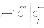
The circuit is not new at all, and is known from the datasheets of the 90s. But the interesting thing about the circuit is that both op amps amplify the same signal. But this is not a bridge connection. The output signals of both op amps are in phase, and their output currents are added.
Such inclusion solves the problem of low output current of many op amps. This significantly increases the number of op amps that can be used in an amplifier. It is now sufficient that each op-amp can supply 35-40 mA of output current, instead of 70-80 for one op amp per channel.
The maximum value of the output current is always given in the datasheet on the op-amp.
Gain
The signal gain is determined by the resistors R1 and R2 ... Its exact value is determined by the formula:
K = 1+ R2 / R1
If you focus on a linear output with a signal level of 1 Volt, then for most headphones, a gain of three will be quite enough. We will equalize by three.
It is desirable that the resistors that set the gain have an accuracy not worse than ± 1% ... There are often not too many precision resistors available in stores. But in this case, you can get by with resistors of the same rating.
In the bins of the cabinet, precision resistors of 7.5 kOhm were found, which became a resistor R1 ... As R2 two 7.5 kΩ resistors were connected in series. The same can be done by connecting in parallel two 15 kOhm resistors as R1 , and one 15k ohm resistor as R2 .
To change the gain, it is better to change the resistor R2 ... For op-amp circuits, it is usually recommended to use resistors with a nominal value of 1 ÷ 100 kOhm. Resistor R1 will perform another important function, therefore preferably 7.5kΩ.
We bring the scheme to mind
The diagram presented in the document is somewhat incomplete and reflects only the most important thing. For normal operation, the circuit should be supplemented with input circuits, as well as parallel to the resistor R2 a small capacitor should be added. It is needed to exclude self-excitation of the op-amp.
For starters, let's not reinvent the wheel and borrow the input circuit from the headphone amplifier. FiiO Olympus E10. In this case, the circuit of our amplifier will take the following form:

The diagram shows the legs for a dual operational amplifier in a DIP8 package. The scheme is completely working and does not need any adjustment.
Let's throw out the capacitor from the input
The op-amp amplifies both AC and DC voltage equally well. Capacitor( C1 ) is needed in order to cut off the DC voltage at the input. On the one hand, normal signal sources do not provide a constant output. On the other hand, if it suddenly appears, then it needs to be cut off. And even the headphones can be burned.
But people actively do not want to see extra capacitors in the signal path, so we will get out.

Rereading once again " The art of circuitry Horowitz and Hill, found what he was looking for. To get an AC amplifier, you need to include a capacitor similar to C1 , in series with the resistor R1.
In this case, the feedback of the op-amp will work only on change and the need for a capacitor at the input will disappear. Therefore, you can safely move C1 from the input of the amplifier to the feedback circuit of the op-amp.

Formed ( R1 , C1 ) will cut off both DC voltage and infra-low frequencies ( <10Гц ). They do not carry useful information, but they significantly load the amplifier in terms of current.
Also, this inclusion of the capacitor will reduce the voltage of the op-amp unbalance at the inputs. And it, by the way, is also amplified and mixed into the output signal. In this case, the capacitor in the feedback circuit has practically no effect on the sound, in contrast to the capacitor at the input. In general, some poles from such a permutation.
Input resistors
Removing the capacitor from the input forced a closer look at the resistors R5 and R6, remaining at the entrance. And why are they needed at all and how to calculate them?
Resistor R5 called compensating and is necessary to ensure equal resistance between each of the inputs and ground. Its value is defined as the parallel resistance of the resistors R1 and R2 .

However, we have consistently with R1 there is a capacitor C1. The resistance of the capacitor depends on the frequency and is added to the resistance of the resistor. The resistance of a capacitor at a certain frequency is determined from the ratio:
R С = 1 / (2 × π × F × C),
Where F in Gegrtsy, WITH in Farads, and R C in Omah
To determine resistance R5, first, the values of the resistances of a 2.2 μF capacitor were calculated at frequencies of 20 Hz and 20 kHz. Then, for both cases, the values of the compensating resistors were calculated. It turned out that the resistance of the resistor R5 should lie between 8.91 k Ohm (for 20 Hz) and 6.81 k Ohm (for 20kHz). Without hesitation stuck 7.5 kΩ.
With a capacitor, we decoupled the inverting input of the amplifier from the DC ground. But the op-amp must be connected to ground in both AC and DC. This is what the resistor is for. R6 ... Its value was chosen equal to 75 kOhm. But you can also put 100 kOhm. Less than 75 kOhm, with a variable change of 50 kOhm, I would not recommend setting it. Together with a resistor R5 they will begin to bypass the input variable resistor.

In the diagram, the output was also slightly changed. The values of R3 and R4 were reduced to 10 ohms, and a resistor R7 with the same resistance was connected in series with them. This should provide a better summation of the output signals.
Amplifier power
The quality of the food is very important for the sound. This circuit is designed for a bipolar supply voltage. This saves us from having to add unnecessary detail to the audio path, and is generally better for the sound.
Op-amps exist today that operate from ± 1.5V, but most opamps operate on a bipolar supply voltage of ± 3V to ± 18V. The optimum voltage can be called ± 12V, which is included in the supply range of most op amps.
The exact values of the maximum supply voltage should be found in the documentation for specific microcircuits.

Component quality
It is not necessary to immediately purchase expensive parts. To begin with, you can put something from the assortment of the nearest radio parts store, and gradually replace them with better components. The board will work on any details.
Capacitor C1 must be non-polar. Better polypropylene or film. It is better to use a ceramic capacitor C2. The accuracy of the capacitors is not very important. but it is better to use it with an accuracy of at least 5%.
Op-amp prices vary widely and doesn't always mean better for sound. To begin with, you can install something inexpensive and affordable, for example, the beloved by many NE5532 ($ 0.3). It is highly desirable that it be produced by Phillips.
Subsequently, with the replacement of the op-amp, you can play as much as you want. If we consider the op-amp as a higher class, then OPA2134, OPA2132, OPA2406, AD8066, AD823, AD8397 ... have proven themselves well for sound.
I do not recommend ordering microcircuits from Aliexpress and other Chinese stores. There are quite a few reviews in which people report that the microcircuits are not original. Yes, the op-amp will work as it should, but it may not be the OPA2134 you ordered at all, but a rather cheap TL061 labeled OPA2134 ...
Conclusion
The resulting amplifier circuit, assembled on the OPA2132 and operating even at a supply voltage of ± 5V, freely rocks the rather tight Sennheiser HD380 Pro.
I do not like to describe the sound in subjective terms like "highs became crystal" or "bass warm", I can only say that when using a good op-amp, this headphone amplifier has a sufficient margin of volume and output power. At the same time, it does not require any tuning and uses a minimum of details, while providing decent sound quality.
The considered scheme led to the idea of creating a portable headphone amplifier. So came up with ... The essence of which is to create a complete design of a portable headphone amplifier with your own hands from scratch.
Material prepared exclusively for the site
We all love to listen to music on headphones, since it is not always possible to turn it on in the speakers, especially at late hours of the day or on public transport. But the sound quality itself is not always good enough, one of the signs of this is the built-in amplifier in the playback device, be it a phone or a computer, laptop. In this article, I will tell you how to make a headphone amplifier with your own hands, in the assembly of which a kit kit will help, you can order it using the link at the end of the article.
In order to make a headphone amplifier with your own hands, you will need:
* Soldering iron, flux, solder
* Third hand soldering attachment
* Side cutters
* Thinner 646 or gasoline "galosh"
* Power supply with output voltage 12V
* Headphones, phone or other playback device
Step one.
This kit comes with a double-sided PCB, the quality is very good and has plated holes. Also, for ease of assembly, an instruction is provided, which shows the amplifier circuit and component ratings for correct installation on the board.
First of all, we install resistors on the board, their values do not need to be determined, since they are signed on a piece of paper glued to them. Then we insert non-polar ceramic capacitors, and then polar electrolytic capacitors, observing the rating and polarity, the plus is the long lead, and the minus is the contact opposite the white strip on the case, on the board the minus contact is indicated by a shaded semicircle. To indicate the operation of the amplifier on the board, there is a place for a red LED, install the long leg in the place indicated by the triangle, and the minus-short leg in the hole with the strip next to it.

Step two.
In order to prevent radio components from falling out during soldering, we bend their leads on the back of the board. Next, we fix the board in the "third hand" soldering device and apply flux to the contacts, after which we solder the leads using a soldering iron and solder. We remove excess leads using side cutters. Be careful when removing pins with side cutters, as you may inadvertently remove a track from the board.


Then we install the rest of the components, namely a variable resistor, a power supply socket, two sockets for microcircuits, guided by the key on the case and the board in the form of a notch, as well as a socket for connecting the input and output of sound.


We solder the components, apply flux for better soldering. We also remove the excess part of the pins with side cutters.

After soldering, such a board is obtained.

We remove the remnants of the flux from the board using a brush and solvent 646 or gasoline "galosh". This is what the net board looks like.

Step three.
Now we install microcircuits in special sockets according to the key on the case and the board.

Next, we proceed to the assembly of the case, first we try it on the board and remove the protective films from the parts of the case. We fasten the four-hole threaded racks to the bottom using a Phillips screwdriver.


Next, we install a board with a side panel with holes for connection jacks on the racks.

After that, we collect the rest of the parts and fasten the top cover with screws.


On this, the headphone amplifier can be considered ready, it remains to test it.
Step four.
For full operation of the amplifier, a 12V power supply is required.In the socket we connect the power supply through the plug and insert the 3.5 mm Jack plug from both sides, one goes into the phone, the other into the amplifier, into the jack labeled OUT we insert the plug from the headphones and enjoy high-quality sound. Volume control is carried out by turning the variable resistor knob.
Probably many of you have faced such a problem when, having connected your headphones to an MP3 player or phone, the volume was insufficient, in other words, the power of the player or phone was not enough to provide loud, clear sound. And what about this case?
To do this, you can assemble a headphone amplifier with your own hands. Its scheme is quite simple and any radio amateur, no matter whether a beginner or an experienced one, can make it, showing accuracy and attentiveness.
When creating this amplifier, I wanted to make it unusual, I wanted to move away from the classic plastic case. Remembering that computer modders often make transparent cases for their PCs, I also decided to make the case of my amplifier transparent. And as a highlight - to abandon the printed circuit board and do everything with surface mounting.
The development of the circuit was carried out in the program Eagle... This is a classic dual opamp amplifier OPA2107.
Below is a diagram of a DIY headphone amplifier:

List of required parts for the amplifier power supply:
- Power connector;
- 5 mm LED (any color);
- R1LED - resistor rated from 1K to 10K (1 W);
- CP1, CP2 - electrolytes 470 μF (for a voltage of 35 or 50 volts);
- RP1, RP2 - 4.7K (1W);
Amplifier Parts List:
- IC1 - OPA2107 dual operational amplifier;
(note - on the schematic diagram, the operational amplifier is designated as OPA2132, the fact is that at first I planned to use it); - C1L, C1R - 0.68 uF 63 V (for input audio signal);
- C2, C3 - 0.1 μF (film, to stabilize the operational amplifier);
- R2L, R2R - 100K (0.5 W);
- R3L, R3R - 1K (0.5 W);
- R4L, R4R - 10K (0.5W);
- R5L, R5R - jumper (optional);
- Stereo jack - 2 pcs;
Since I decided to do everything by hanging installation, I started making the frame. Here you need to be careful and attentive, because the case will be transparent and any imperfections will be immediately visible.
For the power rail, I used 1mm thick solid copper wire taken from cable cuttings used for household wiring.

Any transformer power supply with a voltage of 12 Volts and an output current of 300 mA or more is perfect as a power supply. It is advisable to use a transformer PSU, since the use of impulse power supplies can lead to interference (a constant hum in the headphones will be heard).
For the power connector, I used the following connector: (the center pin is the power plus).

In order to form the same leads of resistors and wires, I used an ordinary screwdriver. You can use different diameters for larger or smaller radii.


Below you can see the layout of the power supply. At the input of the power supply 12 Volts, which are then converted to +6 Volts and -6 Volts using a voltage divider (resistors RP1 and RP2, 4.7 kΩ each). The point is that the op-amp requires a bipolar power supply. The wire in the center is the so-called "virtual ground" and should never be connected to real ground (at the power connector).


Two large capacitors of 470 μF 50 Volts paired with 0.1 μF capacitors are necessary in order to reduce pickup on the op amp and increase its stability. To do this, you need to try to place them as close as possible to the outputs of the op-amp.

Here are a few more photos from different angles, which show how I performed the editing.


After you have finished soldering, you can start checking the amplifier. A small tip, you don't need to use your coolest headphones for testing, some simple ones are enough. The fact is that if you get confused somewhere and soldered the parts not according to the scheme, then such an option is quite possible in which you ruin your headphones. But I hope that when you check it, everything will be fine.

Since the amplifier will be filled with epoxy in the future, I decided to raise it a little so that when pouring it would be exactly in the center of the case. To do this, I soldered small pins from the bottom.

I thought it would be nice to refine the design of the amplifier a little more, so I decided to print stickers for the audio connectors. I prepared them in Adobe photoshop, then printed on thin photo paper and glued to the connectors with double-sided tape.


For some time I have been thinking about the design of the body and the material from which the fill mold will be made. I opted for 1.5 mm plastic, it is perfectly cut with an ordinary stationery knife, while leaving a very smooth edge.
Then I developed a fill shape using the same Eagle... Having cut out all the parts, I proceeded to the assembly. In order to facilitate this procedure, I first grabbed all the corners with super glue, then glued each seam 2 times, which ensured complete tightness.


The easiest way to find out the volume of epoxy to pour is to fill the mold with water, and then pour the contents into a cup and find out the resulting volume and weight. Of course, you can measure the volume with a ruler - but the method with water seemed easier to me.
I used transparent epoxy for the fill. Specifically for this resin, the ratio of hardener to resin should be 1: 50. It was quite difficult to measure out such a small amount of hardener, jewelry scales came in handy for this. In general, for different brands of epoxy resins, the ratio of hardener and resin is different, see the instructions.


The mixed resin must be poured slowly down the side of the mold to avoid bubbles. The picture below shows that when pouring the resin, I poured a little more than required, the resin does not pour out due to the surface tension. This is because the epoxy resin hardens slightly in size.


When the epoxy hardens, there is an abundant release of heat (in my case, the temperature was 62 degrees). The mold is then covered to prevent dust and debris from entering the surface.


I left the epoxy to harden for a day. After this time, it dried up and I started to remove the form. For this I used a belt sander.


Then, using a router, I grinded off the chamfers and all sharp corners.


To polish the case, I first used 600 grit sandpaper, and the final polishing was carried out "on wet" with 1200 fine-grained sandpaper.


And finally, here are some more photos of the finished do-it-yourself headphone amplifier:


Now you know how to make a headphone amplifier with your own hands.
Why you need a camera when you have a phone, unfortunately, not everyone understands. And even fewer people understand why a headphone amplifier is needed. We will not only consider why you need it, but also assemble an inexpensive and high-quality portable headphone amplifier. So simple that everyone can do it ...
Headphone Amplifier Vol.X © - Attempt to write an article in real time as the project progresses. Comments are welcome!
Follow the progress in .
As the project progresses, the article will be supplemented with the necessary material. The ultimate goal is to create a complete structure, easy to repeat, high quality portable headphone amplifier. The emphasis is on the ability to implement the amplifier by a person not possessing deep knowledge of electronics.
If you understand all the salt of pictures walking on the Internet, then you can also assemble an amplifier :-).

Why is the amplifier called Vol.X ©? -Do not know. It was just decided to give a specific name to this project. Sounds more solid. Maybe over time it will come to Vol.X2. Who knows…
Loudness is not the main goal
Many people think that a headphone amplifier is needed only for louder listening to music. In fact, the value of this gadget is somewhat higher.Any headphones are a complex load for a sound source. This statement is even more true if the headphones are reinforcing, hybrid, iso- / ortho-dynamic or more exotic.
The main problem is usually the lack of output current of the sound source. On the other hand, most modern sources cannot provide a signal of sufficient level to drive high-impedance headphones, for example .

To summarize, the main task of a headphone amplifier is to match the signal source with the headphones. In this case, the original sound quality should be preserved, and the output signal should have a higher power than the input.
Let's make our life easier
Those who are just discovering electronics and high-quality sound will certainly be pleased with the fact that an amplifying part will need to be assembled. And even then later, a printed circuit board and all other necessary information will be given, ready for repetition.
The rest of the nodes will be purchased ready-made.This will greatly simplify and reduce the cost of the task without any loss of quality. Self-assembly of such units will considerably complicate the task. And to do without them in the conceived design will not work.
In addition, with the current scale of production of various modules, the cost of purchasing parts for such a module is more expensive than the cost of a finished module. A reasonable question arises - why take a steam bath?)
Op amp headphone amplifier
The most convenient option are circuits based on operational amplifiers (op amps). In this case, the number of elements is minimized, and the circuit does not require any adjustment.
A big plus of operational amplifiers is that all of them, with the exception of specialized ones, are available in DIP8 (Minidip) and SO-8 (aka SOIC) packages.

We will focus on the DIP8 package. It is larger in size. Therefore, firstly, it is easier to solder, and secondly, it cools better, which is also important for an amplifier. And for those microcircuits that are not produced in DIP8, you can use .

The purpose of the op-amp pins is standardized and they are interchangeable. Therefore, you can solder the sockets for the microcircuits once and simply insert the mikruhi without the help of a soldering iron. This will not only simplify the replacement of microcircuits, but also save them from possible overheating during soldering.

Headphone amplifier circuit

Where did this scheme come from and why each specific detail is needed was described in detail in the article: .
Amplifier power
The power supply directly determines the sound quality of the amplifier. Of course, it is better to use a higher supply voltage, which is also bipolar.For a portable design that will be powered by a single battery, a good voltage can be considered± 5 volts.
This will be with a margin for the buildup of most headphones, but at the same time such power will be pulled by the battery. To obtain the required voltage, we will use a dc-dc converter.
DC-DC converter Is a device capable of converting a constant voltage of one magnitude into a constant voltage of another magnitude.
DC-DC converter
Two interesting microcircuits of dc-dc converters have already been considered, this and.In order not to worry about assembling unnecessary circuits, we will use a ready-made cheap and very tasty DC-DC converter module.
It was originally planned to use this module with very interesting declared characteristics. But there were some doubts with battery power, and the $ 9 price tag was a little annoying. The other day another module was received, which exceeded all expectations.

Such a miracle costs only $ 3. There are a lot of sellers selling this module on Aliexpress. When ordering, I simply focused on the lowest side. After receiving it, I realized that it was the official store of the module manufacturers. Therefore, I recommend ordering in the store.
Modules are sold for ready-made voltages ± 5, ± 6, ± 9, ± 12, ± 15 or ± 24 volts. If necessary, it can be changed by soldering the resistor R1.
The parameters depend on the selected output voltage. For the ± 5 volt module of interest to us, the input voltage should be 3-4.5 V. In this case, the output current can reach 1A for positive voltage and 200mA for negative polarity. Which is just right for us.

The real characteristics and a detailed description of the module's capabilities will soon be discussed in a separate article. In the meantime, I can say that this module pulled 6 dual op amps, two of which made up the amplifier described in the article. There is no background, and the voltage drawdown is minimal. So the module is definitely worth its money.
The next step is to select a case.
At the moment, the development of the circuit is completed, the power module is awaiting testing, and I am waiting for the case and other components.
Follow the project news on Twitter
A small guitar amplifier based on JFET transistors and an LM386 microcircuit in a 1 watt power amplifier can be assembled according to the following diagram and instructions. The preamplifier input stages on two J201 transistors provide almost a tube sound, the adjustable tone block has a large range, and the powerful LM386 op-amp with an output stage can drive a small speaker or any headphones. This project is ideal as a small homemade one, with all the main functions of branded devices:
- Tone / volume / gain are adjustable.
- Speaker / headphone output.
- Guitar / mp3 inputs.
- 9 V DC power supply - standard input jack.
Electric guitar amplifier circuit
PCB drawing (no file)

The circuit can be conditionally divided into 5 blocks: an input stage with JFET transistors, a tone control, a preamplifier, an LM386 power amplifier and a power supply. The input stage isolates the amp from the guitar while maintaining signal quality. The tone control then shapes the frequency response you want, adding more bass / treble as needed.

On JFET transistors, the preamplifier will increase the signal after the tone control and prepare it for the power amplifier, resulting in up to 1W. An additional AUX / MP3 input allows you to connect a metronome, MP3 player, and support for external audio tracks.
ULF power supply
The power supply unit outputs 9 volts to all elements of the circuit, there is also protection against reverse polarity of the connection and an additional filter is installed to remove the slightest noise.

CONN4 can accept any type of 9V (negative polarity) adapter, it will automatically disconnect the battery from the circuit when an external 9V AC adapter is plugged into it.
The stereo guitar input jack is used as a switch, connecting the (-) terminal of the battery to ground when the electric guitar is connected.
Diode D1 - protects the amplifier against accidental reverse connection of the power supply. D2 LED lights up when 9V battery or adapter + guitar are connected. Use a larger resistor R14 to minimize the current.

The volume at the AUX input is adjustable from an external device, this is done for simplicity of circuit design and to reduce the level of possible interference.
Output attenuator LM386
The output power of the LM386 is too high for headphones for this, the signal can be attenuated. Output attenuator frequency response:

As you can see, the output attenuator changes the frequency response, reducing the amount of unnecessary bass in the headphones. No attenuator (purple section): low pass filter formed by C7 (220uF) and speaker (we will treat it as 8 ohms), cutoff frequency 90Hz (calculated as FC = 1 / (2nRC)), and harmonics below 90Hz will be attenuated ...
Customization

This wiring diagram shows the required voltages at the test points of the circuit, which should be with error-free assembly.
Discuss the article GUITAR HEADPHONE AMPLIFIER