7.20 *. Engineering networks should be placed mainly within the cross-sections of streets and roads; under sidewalks or dividing strips - utilities in collectors, canals or tunnels; in the dividing lines - heating networks, water supply, gas pipelines, utility and rain sewers.
On the strip between the red line and the building line, low pressure gas and cable networks (power, communications, signaling and dispatching) should be placed.
If the width of the carriageway is more than 22 m, it is necessary to provide for the placement of water supply networks on both sides of the streets.
7.21. When reconstructing carriageways of streets and roads with the installation of road capital pavements, under which underground engineering networks are located, it is necessary to provide for the removal of these networks to the dividing strips and under the sidewalks. With appropriate justification, it is allowed to preserve existing networks under carriageways, as well as to lay new networks in canals and tunnels. On existing streets that do not have dividing stripes, it is allowed to place new engineering networks under the carriageway, provided they are placed in tunnels or canals; if it is technically necessary, it is allowed to lay a gas pipeline under the carriageways of the streets.
7.22 *. The laying of underground engineering networks should, as a rule, provide for: combined in common trenches; in tunnels - if it is necessary to simultaneously place heating networks with a diameter of 500 to 900 mm, a water supply system up to 500 mm, more than ten communication cables and ten power cables with a voltage of up to 10 kV, during the reconstruction of main streets and areas of historical development, with a lack of space in the cross-section of streets for placing networks in trenches, at intersections with main streets and railways. In the tunnels, it is also allowed to lay air ducts, pressure sewerage and other engineering networks. Joint laying of gas and pipelines transporting flammable and combustible liquids with cable lines is not allowed.
In areas where permafrost soils are spread, during the construction of engineering networks with the preservation of soils in a frozen state, it is necessary to provide for the placement of heat pipes in channels or tunnels, regardless of their diameter.
Notes *:
1. On building sites in difficult soil conditions (forest subsidence), it is necessary to provide for the laying of water-carrying engineering networks, as a rule, in walk-through tunnels. The type of soil subsidence should be taken in accordance with SNiP 2.01.01-82; SNiP 2.04-02-84; SNiP 2.04.03-85 and SNiP 2.04.07-86.
2. In residential areas in difficult planning conditions, it is allowed to lay ground heating networks with the permission of the local administration.
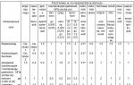
7.23 *. Horizontal distances (in the light) from the nearest underground engineering networks to buildings and structures should be taken according to Table 14. *
The horizontal distances (in the light) between adjacent engineering underground networks when they are placed in parallel should be taken according to Table 15, and at the inputs of engineering networks in buildings of rural settlements - at least 0.5 m. With a difference in the depth of the adjacent pipelines over 0, The 4 m distances indicated in Table 15 should be increased taking into account the steepness of the slopes of the trenches, but not less than the depth of the trench to the bottom of the embankment and the edge of the excavation.
When engineering networks intersect each other, the vertical (clear) distances should be taken in accordance with the requirements of SNiP II-89-80.
The distances indicated in Tables 14 and 15 may be reduced if appropriate technical measures are taken to ensure safety and reliability requirements.
Table 14 *
Table 15

7.24. The intersection of subway structures by utility networks should be provided at an angle of 90 °; in conditions of reconstruction, it is allowed to reduce the intersection angle to 60 °. The intersection of engineering networks of metro station structures is not allowed.
At the intersection, the pipelines must have a slope in one direction and be enclosed in protective structures (steel cases, monolithic concrete or reinforced concrete channels, collectors, tunnels). The distance from the outer surface of the lining of metro structures to the end of protective structures must be at least 10 m in each direction, and the vertical distance (in the light) between the lining or the foot of the rail (with ground lines) and the protective structure must be at least 1 m. under the tunnels is not allowed.
Transitions of engineering networks under underground metro lines should be provided taking into account the requirements of GOST 23961-80. In this case, the networks must be brought out at a distance of at least 3 m outside the boundaries of the fences of the underground metro sections.
Notes:
1. In the locations of the metro structures at a depth of 20 m or more (from the top of the structure to the surface of the earth), as well as in the locations between the top of the lining of the metro structures and the bottom of the protective structures of engineering networks of clay, non-fractured rocky or semi-rocky soils with a thickness of at least 6 m The stated requirements for the intersection of utility networks with metro structures are not imposed, and the device of protective structures is not required.
2. At the intersection of metro structures, pressure pipelines should be made of steel pipes with a device on both sides of the intersection of wells with outlets and installation of stop valves in them.
7.25 *. When crossing underground engineering networks with pedestrian crossings, it is necessary to provide for the laying of pipelines under the tunnels, and power and communication cables - above the tunnels.
7.26 *. The laying of pipelines with flammable and combustible liquids, as well as with liquefied gases for the supply of industrial enterprises and warehouses in the residential area is not allowed.
Trunk pipelines should be laid outside the territory of settlements in accordance with SNiP 2.05.06-85. For oil product pipelines laid on the territory of the settlement, SNiP 2.05.13-90 should be followed.
The horizontal distances (in the light) between adjacent engineering underground networks when placed in parallel should be taken:according to table 5.13;
Not less than 0.5 m at the inputs of engineering networks in the buildings of rural settlements.
If the difference in the depth of the adjacent pipelines is more than 0.4 m, the distances indicated in Table 5.13 should be increased taking into account the steepness of the slopes of the trenches, but not less than the depth of the trench to the bottom of the embankment and the edge of the excavation.
when performing the appropriate technical measures to ensure safety and reliability requirements;
Laying underground gas pipelines with a pressure of up to 0.6 MPa in cramped conditions (when it is not possible to fulfill the distances regulated by regulatory documents) on separate sections of the route, between buildings and under the arches of buildings;
The laying of gas pipelines with a pressure of more than 0.6 MPa when they are brought together with detached ancillary buildings (buildings without the constant presence of people) - up to 50%.
When engineering networks intersect each other, the vertical distance (in the light) should be taken, not less than:
1) when laying a cable line parallel to a high-voltage line (OHL) with a voltage of 110 kV and above from the cable to the end wire - 10 m;
2) between pipelines or electric cables, communication cables and railway tracks, counting from the foot of the rail, or roads, counting from the top of the coating to the top of the pipe (or its case) or electric cable - according to the calculation of the strength of the network, but not less than 0.6 m ;
3) between pipelines and electric cables placed in canals or tunnels, and railways, counting from the top of the overlap of channels or tunnels to the foot of the railroad rails - 1 m, to the bottom of the ditch or other drainage structures or the base of the embankment of the railway roadbed - 0, 5 m;
4) between pipelines and power cables up to 35 kV and communication cables - 0.5 m;
5) between pipelines and power cables with a voltage of 110-220 kV - 1 m;
6) between pipelines and communication cables when laying in collectors - 0.1 m, while communication cables should be located above the pipelines;
7) between communication cables and power cables with parallel laying in collectors - 0.2 m, while the communication cables should be located below the power cables.
the distance from cable lines to underground parts and earthing switches of individual supports of overhead lines with a voltage above 1000 V is allowed to take at least
2 m, while the horizontal distances (in the light) to the outermost wire of the overhead line are not standardized;
Subject to the requirements of the PUE, the distance between cables of all voltages and pipelines may be reduced to 0.25 m.
Table 5.12
| Network engineering | Distance, m, horizontally (in the light) from underground networks |
||||||||
| to the foundations of buildings and structures | to the foundations of fences of enterprises, overpasses, overhead and communication supports, railways | to the axis of the extreme path | to the side stone of the street, road (edge of the carriageway, fortified shoulder strip) | to the outer edge of the cuvette or the soles of the road embankment | to the foundations of the supports of overhead power transmission lines with voltage |
||||
| railways with a track gauge of 1520 mm, but not less than the depth of trenches to the bottom of the embankment and the edge of the excavation | railways gauge 750 mm | up to 1 kV outdoor lighting, trolleybus overhead | St. 1 to 35 kV | St. 35 to 110 kV and above |
|||||
| Water supply and pressure sewerage | 5 | 3 | 4 | 2,8 | 2 | 1 | 1 | 2 | 3 |
| Gravity sewerage (household and rainwater) | 3 | 1,5 | 4 | 2,8 | 1,5 | 1 | 1 | 2 | 3 |
| Drainage | 3 | 1 | 4 | 2,8 | 1,5 | 1 | 1 | 2 | 3 |
| Associated drainage | 0,4 | 0,4 | 0,4 | 0 | 0,4 | ||||
| Combustible gas pipelines pressure, MPa; | |||||||||
| low to 0.005 | 2 | 1 | 3,8 | 2,8 | 1,5 | 1 | 1 | 5 | 10 |
| middle over 0.005 to 0.3 | 4 | 1 | 4,8 | 2,8 | 1,5 | 1 | 1 | 5 | 10 |
| high: | |||||||||
| over 0.3 to 0.6 | 7 | 1 | 7,8 | 3,8 | 2,5 | 1 | 1 | 5 | 10 |
| over 0.6 to 1.2 | 10 | 1 | 10,8 | 3,8 | 2,5 | 2 | 1 | 5 | 10 |
| Heating network: | |||||||||
| from the outer wall of the channel, tunnel | 2 | 1,5 | 4 | 2,8 | 1,5 | 1 | 1 | 2 | 3 |
| from the shell of the channelless laying | 5* | 1,5 | 4 | 2,8 | 1,5 | 1 | 1 | 2 | 3 |
| Power cables of all voltages and communication cables | 0,6 | 0,5 | 3,2 | 2,8 | 1,5 | 1 | 0,5* | 5* | 10* |
| Channels, communication tunnels | 2 | 1,5 | 4 | 2,8 | 1,5 | 1 | 1 | 2 | 3* |
| External pneumatic waste chutes | 2 | 1 | 3,8 | 2,8 | 1,5 | 1 | 1 | 3 | 5 |
* Refers only to distances from power cables.
It is allowed to provide for the laying of underground engineering networks within the foundations of supports and overpasses of pipelines, a contact network, provided that measures are taken to exclude the possibility of damage to networks in the event of settling of foundations, as well as damage to foundations in an accident on these networks. When placing engineering networks to be laid using construction dewatering, their distance to buildings and structures should be set taking into account the zone of possible violation of the strength of the foundation soils.
Distances from heating networks with channelless laying to buildings and structures should be taken in accordance with SNiP 41-02-2003 "Heating networks".
Distances from power cables with a voltage of 110-220 kV to the foundations of fences of enterprises, overpasses, overhead supports and communication lines should be taken as 1.5 m.
In irrigated areas with non-subsiding soils, the distance from underground engineering networks to irrigation canals should be taken (to the edge
channels), m:
1 - from a gas pipeline of low and medium pressure, as well as from water pipelines, sewerage, drains and pipelines of flammable liquids;
2 - from high-pressure gas pipelines up to 0.6 MPa, heat pipelines, utility and rainwater drainage systems;
1.5 - from power cables and communication cables.
| Network engineering | Distance, m, horizontally (in the light) |
||||||||||||
| up to-to-to-pro-water | before the ca-nalization of the household | before dre-naz and doge-maiden canalization | to gas pipelines pressure, MPa (kgf / well m) | to ka-be-lei si-lo-s all nap-rya-niy | to ka-be-lei connect | to heating networks | to ka-na-lov, then-nne-lei | to the outside stump-vmo-moo-so-ro-pro-vo-dov |
|||||
| bottom up to 0.005 | middle St. 0.005 to 0.3 | high | outdoor ste-nka ka-nala, ton-nela | casing channelless pro-glue |
|||||||||
| St. 0.3 up to 0.6 | St. 0.6 up to 1.2 |
||||||||||||
| 1 | 2 | 3 | 4 | 5 | 6 | 7 | 8 | 9 | 10 | 11 | 12 | 13 | 14 |
| Water pipes | 1,5 | * | 1,5 | 1 | 1 | 1,5 | 2 | 1* | 0,5 | 1,5 | 1,5 | 1,5 | 1 |
| Household canalization | * | 0,4 | 0,4 | 1 | 1,5 | 2 | 5 | 1* | 0,5 | 1 | 1 | 1 | 1 |
| Rain channeling | 1,5 | 0,4 | 0,4 | 1 | 1,5 | 2 | 5 | 1* | 0,5 | 1 | 1 | 1 | 1 |
| Gas lines pressure, MPa: | |||||||||||||
| low to 0.005 | 1 | 1 | 1 | 0,5 | 0,5 | 0,5 | 0,5 | 1 | 1 | 2 | 1 | 2 | 1 |
| 1 | 2 | 3 | 4 | 5 | 6 | 7 | 8 | 9 | 10 | 11 | 12 | 13 | |
| average over 0.005 up to 0.3 | 1 | 1,5 | 1,5 | 0,5 | 0,5 | 0,5 | 0,5 | 1 | 1 | 2 | 1 | 2 | 1,5 |
| high | |||||||||||||
| over 0.3 to 0.6 | 1,5 | 2 | 2 | 0,5 | 0,5 | 0,5 | 0,5 | 1 | 1 | 2 | 1,5 | 2 | 2 |
| over 0.6 to 1.2 | 2 | 5 | 5 | 0,5 | 0,5 | 0,5 | 0,5 | 2 | 1 | 4 | 2 | 4 | 2 |
| Power cables of all voltages | 1* | 1* | 1* | 1 | 1 | 1 | 2 | 0,1-0,5 | 0,5 | 2 | 2 | 2 | 1,5 |
| Communication cables | 0,5 | 0,5 | 0,5 | 1 | 1 | 1 | 1 | 0,5 | 1 | 1 | 1 | 1 |
|
| Heating network: | |||||||||||||
| from the outer wall of the channel, tunnel | 1,5 | 1 | 1 | 2 | 2 | 2 | 4 | 2 | 1 | 2 | 1 |
||
| from shell-free gasket | 1,5 | 1 | 1 | 1 | 1 | 1,5 | 2 | 2 | 1 | 2 | 1 |
||
| Channels, tunnels | 1,5 | 1 | 1 | 2 | 2 | 2 | 4 | 2 | 1 | 2 | 2 | 1 |
|
| External pneumatic-garbage-wires | 1 | 1 | 1 | 1 | 1,5 | 2 | 2 | 1,5 | 1 | 1 | 1 | 1 | |
* It is allowed to reduce the indicated distances to 0.5 m, subject to the requirements of section 2.3 of the PUE.
The distance from the domestic sewage system to the drinking water supply system should be taken, m:
a) to the water supply from reinforced concrete and asbestos-cement pipes - 5;
B) to the water supply from cast iron pipes with a diameter:
Up to 200 mm - 1.5;
Over 200 mm - 3;
B) to the water supply from plastic pipes - 1.5.
With parallel laying of gas pipelines for pipes with a diameter of up to 300 mm, the distance between them (in the light) is allowed to be 0.4 m and more than 300 mm - 0.5 m when two or more gas pipelines are jointly placed in one trench.
Table 5.13 shows the distances to steel gas pipelines. The placement of gas pipelines from non-metallic pipes should be provided in accordance with SNiP 42-01-2002 "Gas distribution systems".
For special soils, the distance should be adjusted in accordance with SNiP 41-02-2003 "Heating networks", SNiP 2.04.02-84 * "Water supply. External networks and facilities ", SNiP 2.04.03-85 *" Sewerage. External networks and facilities ":
1) between pipelines for various purposes (with the exception of sewage pipelines that cross water pipelines and pipelines for poisonous and foul-smelling liquids) - 0.2 m;
2) pipelines transporting potable water should be placed above sewer or pipelines transporting poisonous and foul-smelling liquids, by 0.4 m;
3) it is allowed to place steel pipelines enclosed in cases transporting drinking water below the sewer, while the distance from the walls of the sewer pipes to the edge of the case should be at least 5 m in each direction in clay soils and 10 m in coarse and sandy soils , and sewer pipelines should be made of cast iron pipes;
4) the inlets of the domestic drinking water supply with a pipe diameter of up to 150 mm may be provided below the sewer without a case, if the distance between the walls of intersecting pipes is 0.5 m;
5) for channelless laying of pipelines of water heating networks of an open heat supply system or hot water supply networks, the distance from these pipelines to the sewer pipelines located below and above should be taken as 0.4 m;
6) when crossing channels or tunnels for various purposes, gas pipelines should be placed above or below these structures at a distance of at least 0.2 m in cases extending 2 m to both sides from the outer walls of the channels or tunnels. It is allowed to lay underground gas pipelines in a case with a pressure of up to 0.6 MPa through tunnels for various purposes.
* Taking into account the use of one lane for car parking.
Notes (edit)
1 The width of streets and roads is determined by calculation depending on the intensity of traffic and pedestrians, the composition of elements placed within the transverse profile (carriageways, technical lanes for laying underground communications, sidewalks, green spaces, etc.), taking into account sanitary and hygienic requirements and civil defense requirements. As a rule, the width of streets and roads in red lines is taken m: main roads - 50-75; main streets - 40-80; streets and roads of local importance - 15-25.
2 In conditions of difficult terrain or reconstruction, as well as in areas with a high urban planning value of the territory, it is allowed to reduce the design speed for high-speed roads and streets of continuous movement by 10 km / h with a decrease in the radii of curves in the plan and an increase in longitudinal slopes.
3 For the movement of buses and trolleybuses on main streets and roads in large, large and large cities, an extreme lane with a width of 4 m should be provided; for passing buses during rush hours at an intensity of more than 40 units / h, and in conditions of reconstruction - more than 20 units / h, it is allowed to arrange a separate carriageway with a width of 8-12 m.
On main roads with a predominant movement of trucks, it is allowed to increase the width of the traffic lane up to 4 m.
4 In climatic subareas IA, IB and IG, the largest longitudinal slopes of the carriageway of main streets and roads should be reduced by 10%. In areas with a volume of snow supply during the winter of more than 600 m / m within the carriageway of streets and roads, strips up to 3 m wide should be provided for storing snow.
5 The width of the pedestrian part of sidewalks and paths does not include the areas required for the placement of kiosks, benches, etc.
6 In climatic subareas IA, IB and IG, in areas with a volume of snowfall of more than 200 m / m, the width of sidewalks on main streets should be taken at least 3 m.
7 In conditions of reconstruction on streets of local importance, as well as with an estimated pedestrian traffic of less than 50 people / h in both directions, it is allowed to arrange sidewalks and paths 1 m wide.
8 When sidewalks are directly adjacent to the walls of buildings, retaining walls or fences, their width should be increased by at least 0.5 m.
9 It is allowed to provide for the gradual achievement of the design parameters of main streets and roads, traffic intersections, taking into account the specific dimensions of traffic and pedestrians with the obligatory reservation of the territory and underground space for prospective construction.
10 In small, medium and large cities, as well as in conditions of reconstruction and when organizing one-way traffic, it is allowed to use the parameters of main streets of district significance for the design of main streets of city-wide significance.
Minimum clear distances from pipelines to building structures and to adjacent pipelines
| Nominal diameter of pipelines, mm | Distance from the surface of the heat-insulating structure of pipelines, mm, not less | ||||
| up to the wall | before overlap | to the floor | to the surface of the thermal insulation structure of the adjacent pipeline | ||
| vertically | horizontally | ||||
| 25-80 | |||||
| 100-250 | |||||
| 300-350 | |||||
| 500-700 | |||||
| 1000 - 1400 | |||||
| Note - When reconstructing heat points using existing building structures, a deviation from the dimensions indicated in this table is allowed, but taking into account the requirements of clause 2.33. |
table 2
Minimum width of aisles
| Name of equipment and building structures, between which passages are provided | Clear passage width, mm, not less |
| Between pumps with electric motors up to 1000 V | 1,0 |
| The same, 1000 V and more | 1,2 |
| Between the pumps and the wall | 1,0 |
| Between pumps and switchboard or instrumentation panel | 2,0 |
| Between protruding parts of equipment (water heaters, mud collectors, elevators, etc.) or protruding parts of equipment and the wall | 0,8 |
| From the floor or ceiling to the surface of the thermal insulation structures of pipelines | 0,7 |
| For servicing fittings and expansion joints (from the wall to the fitting flange or to the expansion joint) with pipe diameter, mm: | |
| up to 500 | 0,6 |
| from 600 to 900 | 0,7 |
| When installing two pumps with electric motors on the same foundation without a passage between them, but with the provision of passages around the double installation | 1,0 |
Table 3
The minimum clear distance between pipelines and building structures
| Name | Clear distance, mm, not less |
| From protruding parts of fittings or equipment (taking into account the thermal insulation structure) to the wall | |
| From protruding parts of pumps with electric motors up to 1000 V with a discharge pipe diameter of no more than 100 mm (when installed against a wall without a passage) to a wall | |
| Between protruding parts of pumps and electric motors when installing two pumps with electric motors on the same foundation against a wall without a passage | |
| From the valve flange on the branch to the surface of the thermal insulation structure of the main pipes | |
| From the extended valve spindle (or handwheel) to the wall or ceiling at mm | |
| The same, for mm | |
| From the floor to the bottom of the insulating reinforcement structure | |
| From wall or from valve flange to water or air outlet | |
| From the floor or ceiling to the surface of the insulating structure of the branch pipes |
APPENDIX 2
PROCEDURE FOR DETERMINING THE DESIGNED THERMAL EFFICIENCY OF WATER HEATERS OF HEATING AND HOT WATER SUPPLY
1. The calculated thermal performance of water heaters, W, should be taken according to the calculated heat fluxes for heating, ventilation and hot water supply, given in the design documentation of buildings and structures. In the absence of design documentation, it is allowed to determine the calculated heat fluxes in accordance with the instructions of SNiP 2.04.07-86 * (for enlarged indicators).
2. The design thermal performance of water heaters for heating systems should be determined at the design outside air temperature for heating design, ° С, and taken according to the maximum heat fluxes determined in accordance with the instructions in clause 1. With independent connection of heating and ventilation systems through a common water heater, the calculated thermal performance of the water heater, W, is determined by the sum of the maximum heat fluxes for heating and ventilation:
![]() .
.
3. The estimated thermal performance of water heaters, W, for hot water supply systems, taking into account heat losses by supply and circulation pipelines, W, should be determined at water temperatures at the break point of the water temperature graph in accordance with the instructions in clause 1, and in the absence of design documentation - according to heat fluxes determined by the following formulas:
For consumers - according to the average heat flow for hot water supply for the heating period, determined according to clause 3.13, and SNiP 2.04.01-85, according to the formula or depending on the adopted heat supply in the tanks according to Appendix 7 and 8 of the specified chapter (or according to SNiP 2.04.07-86 * -);
For consumers - according to the maximum heat flows for hot water supply, determined according to clause 3.13, b SNiP 2.04.01-85, (or according to SNiP 2.04.07-86 * - ![]() ).
).
4. In the absence of data on the amount of heat loss by pipelines of hot water supply systems, heat flows for hot water supply, W, are allowed to be determined by the formulas:
in the presence of storage tanks
in the absence of storage tanks
where is the coefficient taking into account the heat loss by pipelines of hot water supply systems, taken according to table. one.
Table 1
In the absence of data on the number and characteristics of water-folding devices, the hourly consumption of hot water for residential areas may be determined by the formula
where is the coefficient of the hourly unevenness of water consumption, taken from Table 2.
Note - For hot water supply systems serving both residential and public buildings, the hourly unevenness coefficient should be taken as the sum of the number of residents in residential buildings and the conditional number of residents in public buildings, determined by the formula
where is the average water consumption for hot water supply during the heating period, kg / h, for public buildings, determined according to SNiP 2.04.01-85.
In the absence of data on the purpose of public buildings, it is allowed when determining the coefficient of hourly unevenness according to table. 2 conventionally, the number of inhabitants is taken with a coefficient of 1.2.
table 2
Continuation of table. 2
APPENDIX 3
PROCEDURE FOR DETERMINING PARAMETERS FOR CALCULATING WATER HEATERS
1. Calculation of the heating surface of heating water heaters, sq. M, is carried out at the temperature of the water in the heating network corresponding to the design temperature of the outside air for the design of heating, and for the design capacity determined according to Appendix 2, according to the formula
2. The temperature of the heated water should be taken:
at the inlet to the water heater - equal to the water temperature in the return pipe of the heating systems at the outside air temperature;
at the outlet of the water heater - equal to the water temperature in the supply pipe of heating networks behind the central heating station or in the supply pipeline of the heating system when installing a water heater in the ITP at the outside air temperature.
Note - With independent connection of heating and ventilation systems through a common water heater, the temperature of heated water in the return pipeline at the inlet to the water heater should be determined taking into account the water temperature after connecting the pipeline of the ventilation system. When the heat consumption for ventilation is not more than 15% of the total maximum hourly heat consumption for heating, it is allowed to take the temperature of the heated water in front of the water heater equal to the temperature of the water in the return pipe of the heating system.
3. The temperature of the heating water should be taken:
at the inlet to the water heater - equal to the water temperature in the supply pipe of the heating network at the inlet to the heat point at the outside air temperature;
at the outlet of the water heater - 5-10 ° C higher than the temperature of the water in the return pipe of the heating system at the design temperature of the outside air.
4. Estimated water consumption and, kg / h, for calculating water heaters for heating systems should be determined by the formulas:
heating water
heated water
With independent connection of heating and ventilation systems through a common water heater, the calculated water flow rate and, kg / h, should be determined by the formulas:
heating water
heated water
where, respectively, are the maximum heat fluxes for heating and ventilation, W.
5. The temperature head, ° С, of the heating water heater is determined by the formula
APPENDIX 4
PROCEDURE FOR DETERMINING PARAMETERS FOR CALCULATING HOT WATER HEATERS CONNECTED IN A SINGLE-STAGE CIRCUIT
1. The calculation of the heating surface of hot water heaters should be made (see Fig. 1) at the water temperature in the supply pipeline of the heating network corresponding to the break point of the water temperature graph, or at the minimum water temperature, if there is no break in the temperature graph, and according to the design capacity, determined according to Appendix 2
where is determined in the presence of accumulator tanks according to the formula (1) of Appendix 2, and in the absence of accumulator tanks - according to the formula (2) of Appendix 2.
2. The temperature of the heated water should be taken: at the inlet to the water heater - equal to 5 ° C, if there are no operational data; at the outlet of the water heater - equal to 60 ° С, and with vacuum deaeration - 65 ° С.
3. The temperature of the heating water should be taken: at the inlet to the water heater - equal to the temperature of the water in the supply pipeline of the heating network at the inlet to the heat point at the outside air temperature at the break point of the water temperature graph; at the outlet of the water heater - equal to 30 ° С.
4. Estimated water consumption and, kg / h, for calculating a hot water heater should be determined by the formulas:
heating water
heated water
5. The temperature head of the hot water heater is determined by the formula
6. The heat transfer coefficient, depending on the design of the water heater, should be determined according to Appendix 7-9.
APPENDIX 5
PROCEDURE FOR DETERMINING PARAMETERS FOR CALCULATING HOT WATER HEATERS CONNECTED IN A TWO-STAGE CIRCUIT
The method for calculating hot water supply water heaters connected to a heating network according to a two-stage scheme (see Fig. 2-4) with a limitation of the maximum flow of network water at the input, used until now, is based on an indirect method, according to which the thermal performance of the first stage of water heaters is determined by the balance load of hot water supply, and stage II - according to the difference in loads between the design and the load of the first stage. At the same time, the principle of continuity is not observed: the temperature of the heated water at the outlet of the first stage water heater does not coincide with the temperature of the same water at the inlet to the second stage, which makes it difficult to use it for machine counting.
The new calculation method is more logical for a two-stage scheme with a limitation of the maximum flow of network water at the input. It is based on the position that at the hour of maximum draw-off with the outside air temperature calculated for the selection of water heaters corresponding to the break point of the central temperature graph, it is possible to stop the supply of heat for heating, and all the network water goes to the hot water supply. To select the required standard size and number of shell-and-tube sections or the number of plates and the number of strokes of plate water heaters, the heating surface should be determined by the design capacity and temperatures of heating and heated water from the thermal calculation in accordance with the formulas below.
1. The calculation of the heating surface, sq. M, hot water heaters should be carried out at the water temperature in the supply pipe of the heating network corresponding to the break point of the water temperature graph, or at the minimum water temperature, if there is no break in the temperature graph, since in this mode there will be a minimum temperature difference and values of the heat transfer coefficient, according to the formula
where is the calculated thermal performance of hot water heaters, determined according to Appendix 2;
Heat transfer coefficient, W / (m2 · ° С), is determined depending on the design of water heaters according to Appendix 7-9;
The mean logarithmic temperature difference between heating and heated water (temperature head), ° C, is determined by formula (18) of this appendix.
2. The distribution of the calculated thermal performance of water heaters between stages I and II is carried out based on the condition that heated water in stage II is heated to a temperature of = 60 ° C, and in stage I - to a temperature determined by a technical and economic calculation or taken at 5 ° C less than the temperature of the supply water in the return pipeline at the break point of the graph.
The estimated thermal performance of water heaters of stages I and II, W, is determined by the formulas:
3. The temperature of the heated water, ° С, after the first stage is determined by the formulas:
with dependent connection of the heating system
with independent connection of the heating system
4. The maximum flow rate of heated water, kg / h, passing through the I and II stages of the water heater, should be calculated based on the maximum heat flow for hot water supply, determined by formula 2 of Appendix 2, and water heating to 60 ° C in the II stage:
5. Heating water consumption, kg / h:
a) for heat points in the absence of ventilation load, the heating water flow rate is assumed to be the same for the I and II stages of water heaters and is determined:
when regulating the supply of heat according to the combined load of heating and hot water supply - according to the maximum consumption of network water for hot water supply (formula (7)) or according to the maximum consumption of network water for heating (formula (8)):
The largest of the obtained values is taken as the calculated one;
when regulating the supply of heat according to the heating load, the calculated consumption of heating water is determined by the formula
![]() ; (9)
; (9)
 . (10)
In this case, the temperature of the heating water at the outlet of the stage I water heater should be checked with the formula
 . (11)
If the temperature determined by formula (11) is below 15 ° С, then it should be taken equal to 15 ° С, and the heating water consumption should be recalculated using the formula
b) for heating points in the presence of a ventilation load, the flow rate of heating water is taken:
for stage I
![]() ; (13)
; (13)
for stage II
6. Heating water temperature, ° С, at the outlet of the stage II water heater:
 . (15)
7. Heating water temperature, ° С, at the inlet to the stage I water heater:
 . (16)
8. Heating water temperature, ° С, at the outlet of the stage I water heater:
 . (17)
9. Average logarithmic temperature difference between heating and heated water, ° С:
 . (18)
APPENDIX 6
PROCEDURE FOR DETERMINING PARAMETERS FOR CALCULATING HOT WATER HEATERS CONNECTED IN A TWO-STAGE CIRCUIT WITH STABILIZATION OF WATER FLOW FOR HEATING
1. The heating surface of water heaters (see Fig. 8) of hot water supply, m2, is determined at the water temperature in the supply pipe of the heating network corresponding to the break point of the water temperature graph, or at the minimum water temperature if there is no break in the temperature graph, since in this mode there will be a minimum temperature difference and values of the heat transfer coefficient, according to the formula
where is the estimated thermal performance of hot water heaters, W, is determined according to Appendix 2;
Average logarithmic temperature difference between heating and heated water, ° С, is determined according to Appendix 5;
Heat transfer coefficient, W / (m2 · ° С), is determined depending on the design of water heaters according to Appendix 7-9.
2. The heat flux to the II stage of the water heater, W, with a two-stage connection scheme for hot water heaters (according to Fig. 8), required only for calculating the heating water consumption, with a maximum heat flux for ventilation no more than 15% of the maximum heat flux for heating is determined by formulas:
in the absence of heated water storage tanks
in the presence of heated water storage tanks
![]() , (3)
, (3)
where - heat losses of pipelines of hot water supply systems, W.
In the absence of data on the magnitude of heat losses by pipelines of hot water supply systems, the heat flow to the II stage of the water heater, W, can be determined by the formulas:
in the absence of heated water storage tanks
in the presence of heated water storage tanks
where is the coefficient taking into account the heat loss by pipelines of hot water supply systems, is taken according to Appendix 2.
3. The distribution of the calculated thermal performance of water heaters between stages I and II, the determination of the design temperatures and water consumption for calculating water heaters should be taken according to the table.
| Name of calculated values | Scope of the scheme (according to Fig. 8) | |
| industrial buildings, a group of residential and public buildings with a maximum heat flow for ventilation more than 15% of the maximum heat flow for heating | residential and public buildings with a maximum heat flow for ventilation no more than 15% of the maximum heat flow for heating | |
| I stage of a two-stage scheme | ||
| Estimated thermal performance of the first stage of the water heater | | |
| , with vacuum deaeration + 5 | ||
| The same, at the outlet of the water heater |  |
|
| Without storage tanks | ||
| With storage tanks | ||
| Heating water consumption, kg / h |  |  |
| II stage of a two-stage scheme | ||
| Estimated thermal performance of the II stage of the water heater | |
|
| Heated water temperature, ° С, at the water heater inlet | With storage tanks Without storage tanks  |
|
| The same, at the outlet of the water heater | = 60 ° C | |
| Heating water temperature, ° С, at the water heater inlet | ||
| The same, at the outlet of the water heater |  |
|
| Heated water consumption, kg / h | Without storage tanks | |
| Heating water consumption, kg / h | With storage tanks in the absence of circulation In the presence of circulation,  | With storage tanks, |
| Notes: 1 In case of independent connection of heating systems, instead of should be taken; 2 The value of subcooling in stage I, ° С, is taken: with storage tanks = 5 ° С, in the absence of storage tanks = 10 ° С; 3 When determining the design flow rate of heating water for stage I of the water heater, water flow rate from ventilation systems is not taken into account; 4 The temperature of heated water at the outlet of the heater in the central heating station and in the central heating station should be taken equal to 60 ° С, and in the central heating station with vacuum deaeration - = 65 ° С; 5 The value of the heat flux for heating at the break point of the temperature graph is determined by the formula |
APPENDIX 7
THERMAL AND HYDRAULIC CALCULATION OF HORIZONTAL SECTIONAL SHELL-PIPE WATER-WATER HEATERS
Horizontal sectional high-speed water heaters in accordance with GOST 27590 with a pipe system of straight smooth or profiled pipes are distinguished by the fact that to eliminate the deflection of the pipes, two-section support partitions are installed, which are part of the tube sheet. This design of the support baffles facilitates the installation of tubes and their replacement in the field, since the holes of the support baffles are located coaxially with the openings of the tube sheets.
Each support is installed with an offset relative to each other by 60 ° C, which increases the turbulization of the coolant flow passing through the annular space, and leads to an increase in the heat transfer coefficient from the coolant to the tube wall, and, accordingly, the heat removal from 1 square meter of the heating surface increases. Brass tubes are used with an outer diameter of 16 mm, a wall thickness of 1 mm in accordance with GOST 21646 and GOST 494.
An even greater increase in the heat transfer coefficient is achieved by using profiled brass tubes instead of smooth brass tubes in the tube bundle, which are made from the same tubes by extruding transverse or helical grooves on them with a roller, which leads to turbulence of the near-wall fluid flow inside the tubes.
Water heaters consist of sections, which are interconnected by rolls along the pipe space and nozzles - along the annular space (Fig. 1-4 of this appendix). The branch pipes can be split on flanges or one-piece welded. Depending on the design, water heaters for hot water supply systems have the following symbols: for a detachable design with smooth tubes - РГ, with profiled ones - РП; for a welded structure - SG, SP, respectively (the direction of flows of heat exchanging media is given in clause 4.3 of this set of rules).

Fig. 1. General view of a horizontal sectional shell-and-tube water heater with turbulator supports
Fig. 2. Constructive dimensions of the water heater
1 - section; 2 - kalach; 3 - transition; 4 - block of supporting partitions; 5 - tubes; 6 - supporting partition; 7 - ring; 8 - bar;

Fig. 3. Kalach connecting

Fig. 4. Transition
An example of a conventional designation of a split-type water heater with an outer diameter of a section body of 219 mm, a section length of 4 m, without a thermal expansion compensator, for a nominal pressure of 1.0 MPa, with a pipe system of smooth tubes of five sections, climatic version UZ: PV 219 x 4 -1, O-RG-5-UZ GOST 27590.
The technical characteristics of the water heaters are given in Table 1, and the nominal dimensions and connection dimensions are given in Table 2 of this Appendix.
Table 1
Technical characteristics of water heaters GOST 27590
| Section body outer diameter, mm | The number of tubes in the section, pcs. | Cross-sectional area of the annular space, sq. M | Cross-sectional area of tubes, sq.m | Equivalent diameter of the interstring space, m | Heating surface of one Section, sq.m, with a length, m | Thermal performance, kW, section length, m | Weight, kg | |||||||||
| Pipe system | ||||||||||||||||
| smooth (version 1) | profiled (version 2) | section length, m | kalacha, execution | transition | ||||||||||||
| 0,00116 | 0,00062 | 0,0129 | 0,37 | 0,75 | 23,5 | 37,0 | 8,6 | 7,9 | 5,5 | 3,8 | ||||||
| 0,00233 | 0,00108 | 0,0164 | 0,65 | 1,32 | 32,5 | 52,4 | 10,9 | 10,4 | 6,8 | 4,7 | ||||||
| 0,00327 | 0,00154 | 0,0172 | 0,93 | 1,88 | 40,0 | 64,2 | 13,2 | 12,0 | 8,2 | 5,4 | ||||||
| 0,005 | 0,00293 | 0,0155 | 1,79 | 3,58 | 58,0 | 97,1 | 17,7 | 17,2 | 10,5 | 7,3 | ||||||
| 0,0122 | 0,00570 | 0,019 | 3,49 | 6,98 | 113,0 | 193,8 | 32,8 | 32,8 | 17,4 | 13,4 | ||||||
| 0,02139 | 0,00939 | 0,0224 | 5,75 | 11,51 | 173,0 | 301,3 | 54,3 | 52,7 | 26,0 | 19,3 | ||||||
| 0,03077 | 0,01679 | 0,0191 | 10,28 | 20,56 | 262,0 | 461,7 | 81,4 | 90,4 | 35,0 | 26,6 | ||||||
| 0,04464 | 0,02325 | 0,0208 | 14,24 | 28,49 | 338,0 | 594,4 | 97,3 | 113,0 | 43,0 | 34,5 | ||||||
| Notes 1 The outer diameter of the tubes is 16 mm, the inner diameter is 14 mm. 2 Thermal performance is determined at a water velocity inside the tubes of 1 m / s, equal flow rates of heat exchanging media and a temperature head of 10 ° C (temperature difference in heating water 70-15 ° C, heated water - 5-60 ° C). 3 The hydraulic resistance in the tubes is not more than 0.004 MPa for a smooth tube and 0.008 MPa for a profiled tube with a section length of 2 m and, accordingly, no more than 0.006 MPa and 0.014 MPa for a section length of 4 m; in the annular space, the hydraulic resistance is 0.007 MPa with a section length of 2 m and 0.009 MPa with a section length of 4 m. 4 The mass is determined at an operating pressure of 1 MPa. 5 Thermal performance is given for comparison with heaters of other sizes or types. |